



Location of fuel tank accessories in vehicles with 1.9 TDI engine
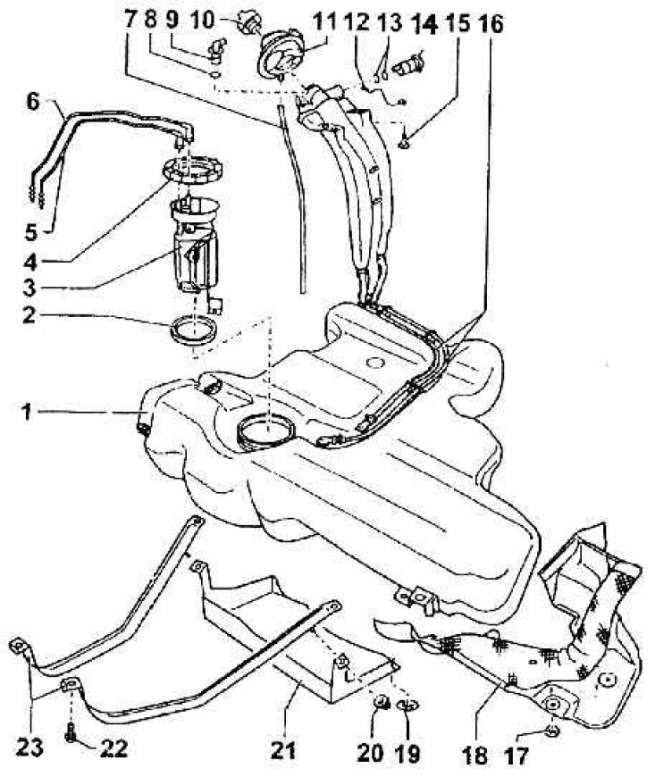
1 – fuel tank; 2 – sealing washer; 3 – fuel level sensor in the tank; 4 – union nut (M = 80 Nm); 5 – fuel line – supply to the engine (painted black); 6 – return fuel line; 7 – air outlet hose; 8 – washer; 9 – combination valve; 10 – filler cap; 11 – elastic washer; 12 – grounding to the body; 13 – washer; 14 – air bleed valve; 15 – ground wire terminal bolt; 16 – air outlet pipe; 17 – mounting gasket; 18 – heat-insulating flap – sheet; 19 – mounting gasket; 20 – nut; 21 – casing; 22 – bolt of the fastening strip (M = 25 Nm); 23 – belts supporting the tank
Fuel tank with auxiliary equipment (engine 1.8 – 92 kW)
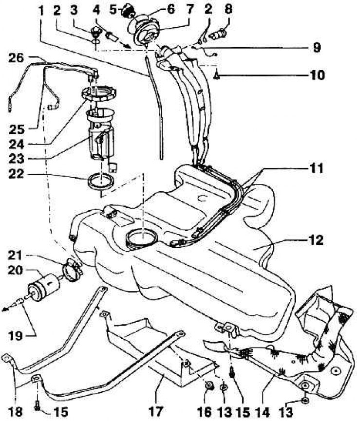
1 – air supply hose to the tank; 2 – sealing washer; 3 – combination valve; 4 – air outlet pipe (to the activated carbon tank); 5 – fuel tank cap; 6 – elastic washer; 7 – rubber seal; 8 – air bleed valve; 9 – grounding to the body; 10 – ground terminal bolt; 11 – air outlet tube; 12 – fuel tank; 13 – mounting gasket; 14 – thermal insulation protection; 15 – protection mounting bolt; 16 – nut; 17 – casing; 18 – fastening belts; 19 – fuel line (to the engine); 20 – fuel filter; 21 – fuel filter mounting clamp; 22 – sealing washer; 23 – fuel pump; 24 – union nut; 25 – fuel line to the fuel filter; 26 – fuel line for return flow of fuel from the engine
Fuel tank - diagram
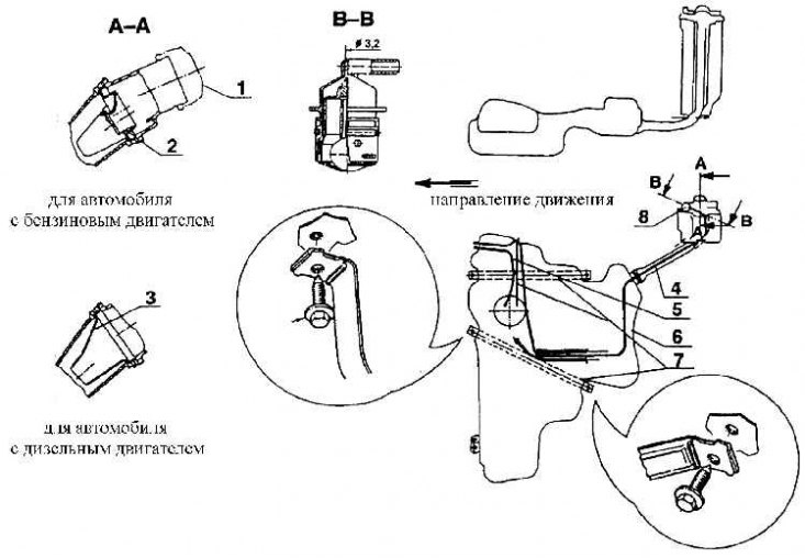
1 – filler cap; 2 - insert limiting the use of the fuel nozzle for leaded gasoline; 3 – insert in the neck of the diesel fuel tank; 4 – air outlet tube; 5 – fuel return line; 6 – fuel line to the engine; 7 – belts for securing the tank; 8 – combination valve
Pipe for removing air from the filler neck
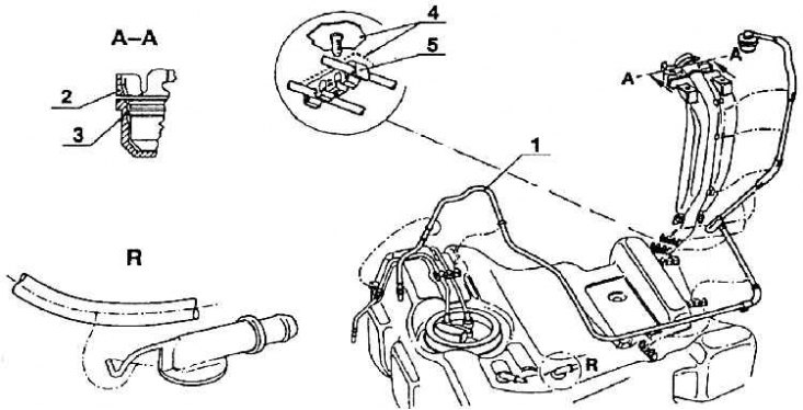
1 – air outlet pipe; 2 – flange with gravity valve; 3 – seal; 4 – floor sheet; 5 – pipeline bracket
Installing a fuel pump in the tank (cars with gasoline engines)
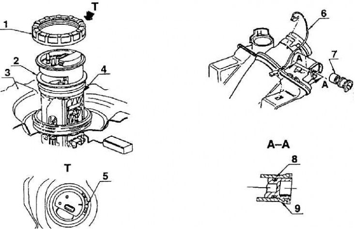
1 – union nut; 2 – seal; 3 – fuel tank; 4 fuel pump; 5 – mounting designation;
Fuel tank filler neck parts: 6 – ground; 7 – air bleed valve; 8 – seal; 9 – installation of air bleed valve
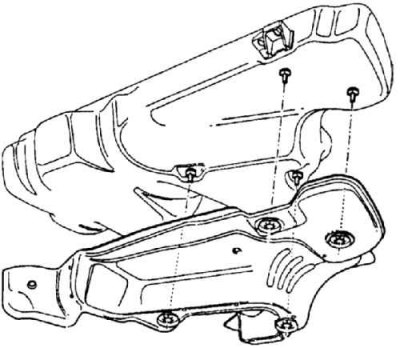
Fuel tank thermal insulation casing
Although the fuel tank is part of the body, it should be thematically related to the fuel system, and therefore it is included in the chapter Fuel System.
The fuel tank is made of plastic (polyethylene TL 669) black. The manufacturing technology allows its molding with the maximum use of the space intended for it. It is located under the rear seats, under the floor in the so-called safety zone. The plastic from which the tank is made does not allow the formation of an electric charge, which is common when using ordinary plastic, therefore, from this point of view, the tank is completely safe. The tank capacity is approximately 55 liters.
Fuel tanks for cars with petrol engines are conceptually no different from tanks for cars with diesel engines. They differ only in the inserts in the filler neck and the fact that an electric fuel pump combined with a level gauge is built into the fuel tank designed for cars with a petrol engine. The tank designed for cars with a diesel engine has only a suction system and a level gauge (the pump is located in the fuel injection system).
The fuel tank assembly also includes the filler neck assembly, the air bleed hose system and the fuel hose.
Electric fuel pump (in the gas tank), as well as a suction system with a level gauge (in the diesel fuel tank) are inserted through a wide opening under the neck in the upper surface of the tank. Both are attached with the same plastic union nut. In the lid there are two nipples for fuel hoses. Through one hose fuel is supplied to the engine, through the other its excess is returned. On the lid and the neck of the tank there is a designation for installation. In the lid there is also a connector for connecting the wiring to the level gauge.
The fuel tank filler neck has a separate ground connection to the body, which protects against electrical breakdown when filling the tank. There is also an insert in the neck. In a gasoline tank, the insert prevents the fuel nozzle intended for leaded gasoline from being put on; in the diesel fuel tank, a funnel-shaped insert prevents fuel from splashing out when filling the tank. The filler neck also contains a combined gravity valve, which allows air to be released, but closes when the vehicle is turned over, thereby preventing fuel from leaking out. The valve cross-section at the outlet is reduced (diameter 3.2 mm) to prevent accidental flame penetration. There is also an air bleed valve in the neck, which is closed during the filling process and opens mechanically when the cap is placed on the neck. The valve prevents the tank from overfilling when refueling.
While the closing cap of the neck is equipped with a patented lock (in some versions of cars), which can be opened with a key common to the door locks and the ignition switch, the key is designed in such a way that the key made for the insert in the plug cannot be used in the door and ignition locks. This prevents the theft of the car with a key made for the insert of the stolen filler cap lock.
The tank is secured in the body cavity with two belts, then with clamps (bolts M8) in the left front part of the tank and two bolts M 6, holding the filler neck at the right rear fender. After unscrewing the mentioned connections, the tank can be removed. Its installation is done in the reverse order.
It is necessary to ensure that none of the hoses are pressed not only because of the ease of filling the tank, but also because of the air supply when pumping out fuel during driving. If air is not supplied to the tank, it may become deformed when pumping out fuel.
An integral part of the tank is a casing, which also serves as thermal insulation from the exhaust.