Attention! The brake pedal travel must not be reduced by additional floor coverings.
Lubricate all bearings with polyurea grease -G 052142 A2- before installing. The brake light switch -F- and the brake pedal switch -F47- are mounted on the brake master cylinder,
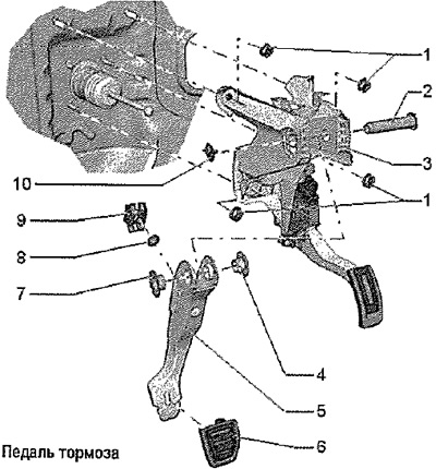
1. Nut, self-locking, 25 Nm: replace after each removal; follow tightening sequence
2. Support pin: Replace after each removal. Removal: Remove support bracket; turn the support pin counterclockwise, the tabs of the support pin break off. Remove support pin.
Carefully! Do not lubricate the bearing pin. The support pin must remain dry; installation is carried out in reverse order. The support pin screw should tighten with a clearly audible click.
3. Support bracket
4. Bearing sleeve. Observe installation position.
5. Brake pedal
6. Cap
7. Bearing sleeve. Observe installation position
8. Bearing shell
9. Nozzle: for the ball head of the push rod of the brake booster
10. Clamp: after each removal, replace
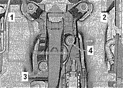
Tightening sequence