



Contents: The main brake cylinder (MBC) with…⬇ Pressure regulator valve located…⬇ Brake fluid reservoir ⬇ Vacuum brake booster ⬇ Front wheel brakes ⬇ Rear wheel brakes ⬇
Diagram of the brake system of models with the location of pressure regulator valves on the master cylinder assembly
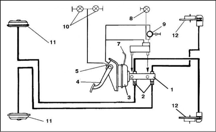
1 - GTZ; 2 - Regulator valves; 3 - Vacuum booster servo drive; 4 - Foot brake pedal; 5 - Brake light switch sensor; 6 - Brake fluid reservoir; 7 - Vacuum tube to intake manifold; 8 - Brake fluid level indicator light; 9 - Ignition switch; 10 - Brake lights; 11 - Rear wheel brakes; 12 - Front wheel brakes
Brake system diagram for models with pressure regulator valve located at the rear axle (the electrical part of the system is similar to the one shown in the illustration above)
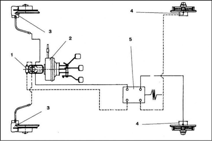
1 - GTZ; 2 - Vacuum booster servo drive; 3 - Front wheel brakes; 4 - Rear wheel brakes; 5 - Regulator valve
GTZ design
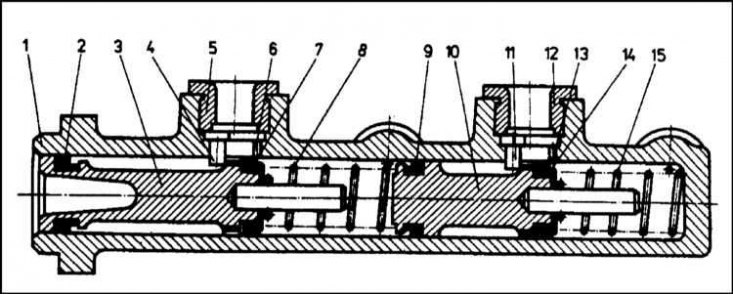
1 - Cylinder; 2 - Sealing cuff; 3 - Piston of the first brake circuit; 4 - Pin; 5 - Sealing bushing; 6 - Inlet; 7 - Sealing cuff; 8 - Spring; 9 - Sealing cuff; 10 - Second brake circuit piston; 11 - Pin; 12 - Sealing bushing; 13 - Inlet; 14 - Sealing cuff; 15 - Spring
Pressure Regulator Valve Components
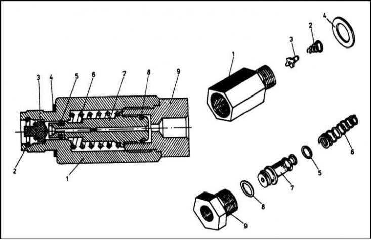
1 - Body (end thread M6x1.5); 2 - Spring; 3 - Rubber valve; 4 - Sealing gasket (16x20 mm); 5 - Sealing ring (8x4 mm); 6 - Spring; 7 - Piston; 8 - Sealing ring (11x7 mm); 9 - Transition nozzle
Design of the brake booster servo drive
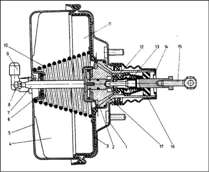
1 - Lid; 2 - Piston; 3 - Diaphragm; 4 - Front (vacuum) chamber; 5 - Body; 6 - Sealing gasket; 7 - Push rod; 8 - Adjusting tip; 9 - Fitting; 10 - Spring; 11 - Back (atmospheric) camera; 12 - Valve; 13 - Valve; 14 - Rubber protective cover; 15 - Control pusher; 16 - Filter; 17 - Channel
Brake booster servo mounting connectors
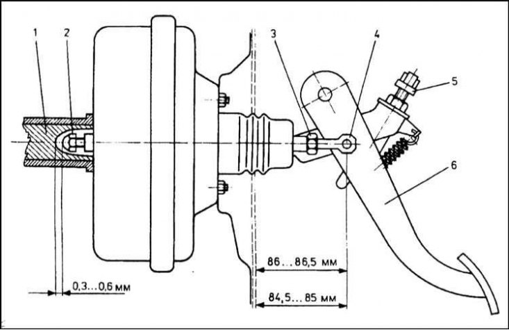
1 - Master cylinder piston; 2 - Pusher adjusting tip; 3 - Lock nut; 4 - Fastening to the foot brake pedal; 5 - Brake light switch sensor; 6 - Foot brake pedal
Brake caliper cylinder
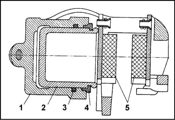
1 - Cylinder body; 2 - Piston; 3 - Sealing cuff; 4 - Dust cover; 5 - Brake pads
Deformations of the piston sealing cuff when the brake mechanism is activated
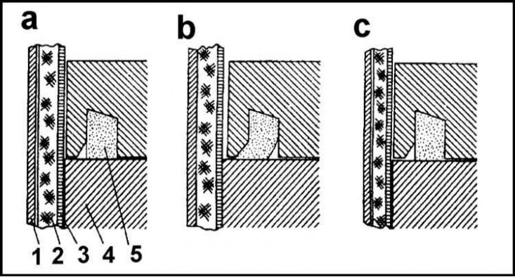
a - Before braking; b - During braking; c - After braking; 1 - Brake disc; 2 - Friction lining; 3 - Base of the shoe; 4 - Piston; 5 - Cuff
Drum brake assembly components
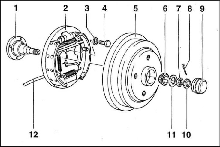
1 - Rear axle hub journal; 2 - Assembling the brake mechanism; 3 - Spring washer; 4 - Bolt (60 Nm); 5 - Brake drum; 6 - Outer wheel bearing; 7 - Hub nut; 8 - Cotter pin; 9 - Wheel hub cap; 10 - Locking crown washer; 11 - Washer; 12 - Parking brake cable
Drum brake assembly components (continuation)
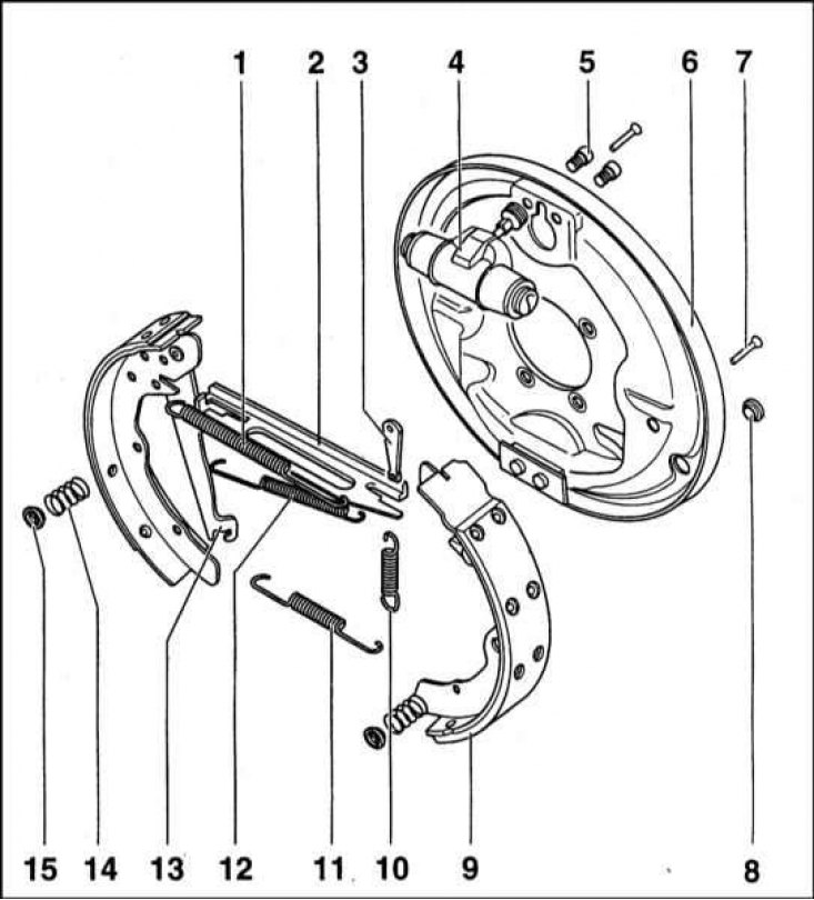
1 - Tension spring; 2 - Expansion bar; 3 - Expansion wedge; 4 - Wheel cylinder; 5 - Hexagon socket head bolt (6 Nm); 6 - Brake shield; 7 - Guide (anchor) pin; 8 - Plug; 9 - Brake shoe; 10 - Expansion wedge spring; 11 - Lower tension spring; 12 - Upper tension spring; 13 - Parking brake actuator; 14 - Guide spring; 15 - Guide spring plate
Section of wheel cylinder
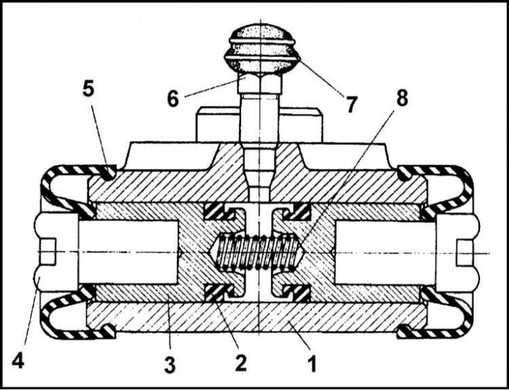
1 - Cylinder body; 2 - Cuff; 3 - Piston; 4 - Pusher; 5 - Dust cover; 6 - Bleed valve; 7 - Rubber protective cap; 8 - Spring
Note: This Section is primarily devoted to describing the design of the brake systems of models not equipped with ABS. Information on the design of ABS is provided in Section Anti-lock Brake System (ABS) - General Information.
The functional diagram of the braking system is shown in the accompanying illustrations.
The system is activated by the foot brake pedal. The force applied to the pedal is transmitted to the 2-piece master cylinder via the vacuum booster servo drive. The increase in pressure of the fluid in the master cylinder is transmitted via hydraulic lines to the cylinders of the brake mechanisms of the front and rear wheels of the car. One or two pressure regulator valves are included in the hydraulic circuit of the rear brake mechanisms.
The vacuum booster is connected to the intake manifold and is designed to increase the force applied to the foot brake pedal and the force exerted on the master cylinder piston.
Regulator valves are used to limit the hydraulic fluid pressure in the rear wheel brake circuit to prevent premature locking of the latter during sudden braking. Note: On models equipped with ABS, there is no need to use such limiters.
The pistons of the front wheel brake calipers act on the brake pads, which are pressed tightly by the friction linings to the working surfaces of the discs. When the pedal is released, the pads return to their original position, releasing the disc and braking stops.
In rear drum brake mechanisms, wheel cylinders are used instead of calipers, the pistons of which expand the brake shoes, pressing them with friction linings to the inner working walls of the drums. When the pedal is released, a special mechanism limits the reverse movement of the shoes, automatically maintaining the gap at a given level.
Due to the described design features, neither the front nor the rear brake mechanisms require additional adjustments.
The parking brake is operated by a lever located between the front seats of the car. The lever is connected by a cable drive to the shoes of the rear wheel brake mechanisms, which brake the car.
The main brake cylinder (MBC) with pressure regulator valves built into it
The brake master cylinder is designed to create pressure of the working fluid in the hydraulic circuits of the vehicle's brake system. The cylinder is secured by means of two M10 nuts on the studs of the vacuum booster servo drive.
The brake master cylinder is made of a cast iron housing with a 22 mm diameter cylinder bore inside, into which the pistons (3) and (10) of the drive of two brake system circuits are placed. Four holes with internal threads are made in the horizontal plane of the brake master cylinder. Two left holes with M6x1.5 threads are intended for screwing in pressure regulator valves in the rear wheel brake circuit. The right holes (M10x1.0) are used to connect the hydraulic lines of the front brake circuits. In the upper part of the brake master cylinder housing, there are sockets equipped with rubber sealing bushings (5) and (12) for fitting brake fluid reservoirs.
The rear section of the master cylinder is connected to the brake mechanisms of the right front and left rear wheels (first hydraulic circuit). Front - to the mechanisms of the left front and right rear wheels (second circuit).
The piston (3) of the first brake circuit drive has a recess for the seating of the tip of the brake booster push rod.
Sealing cuffs (7) and (14) serve to seal the working spaces of the corresponding sections of the master cylinder. Cuff (9) prevents hydraulic fluid from penetrating from one section to another, and cuff (2) prevents air from entering the cylinder.
Springs (8) and (15), installed under the pistons, provide the latter with a reverse stroke. Spring (8), in addition, serves to increase the force applied to the piston of the second section during braking.
Pins (4) and (11) limit the return of the pistons.
When the foot brake pedal is depressed, the movement of the brake booster servo pusher is transmitted to the master cylinder piston (3) and moves it in the cylinder. When shifted, the piston compresses the spring (8), which, together with the increased pressure of the hydraulic fluid, shifts the piston (10). The seals (7) and (14) mounted on the pistons are shifted beyond the inlet openings of the brake fluid reservoirs. As a result, the pressure in both hydraulic circuits of the system increases.
Note: An increase in pressure in the master cylinder causes even stronger pressing of the sealing cuff lips against the cylinder walls, further increasing the tightness of the assembly.
When the pedal is released, the pistons return to their original position under the influence of the forces developed by the springs. The inlet ports communicating with the cylinder cavities open and the hydraulic fluid in the reservoirs freely enters the cylinders, automatically compensating for the increase in the tract volume associated with wear of the friction linings and/or leaks in the lines.
In case of damage to the system, causing depressurization of the first hydraulic circuit, piston (3) will move freely, since the increase in pressure in the working cavity of this section will cease. Piston (10), under the influence of the force developed by the vacuum booster pusher and spring (8), with an increased travel of the foot brake pedal, will ensure the proper functioning of the second hydraulic circuit. In case of a breach of the second circuit's tightness, piston (10), under the influence of the force developed by the pusher and spring (8), overcoming the resistance of the spring (15), will move to the stop with its rod against the end wall of the cylinder. In the first brake circuit, a normal increase in pressure will occur with an increased travel of the brake pedal.
The regulator valve limits the increase in pressure in the brake circuits of the rear wheels, preventing premature locking of the latter. The valve body is screwed into the outlet opening of the master brake cylinder. The tightness of the joint is ensured by a sealing gasket (4). An adapter is screwed into the outlet opening of the regulator valve body, providing the ability to connect to the brake line assembly. The brake fluid, entering the inlet opening of the regulator, passes into the cavity between the rubber valve (3) and the inner wall of the housing. Then the fluid gets inside the channel provided in the piston (7) and then - into the brake line of the hydraulic circuit of the brake mechanism of the corresponding rear wheel. The spring (6) is selected in terms of compression force in such a way that at a fluid pressure of up to 20 kgf/cm² it remains at a distance from the valve. With a further increase in pressure, the spring is finally compressed and the piston is pressed against the valve, which closes the through internal opening in it. As soon as the pressure in front of the piston exceeds the pressure behind the piston by a sufficient amount, the latter moves again, opening access of liquid to the circuit. Then the cycle is repeated the required number of times during the process of braking the car.
Due to this operation of the control valves, the pressure in the brake calipers of the front wheels always remains no lower than in the wheel cylinders of the rear mechanisms, which eliminates the possibility of the latter skidding.
Pressure regulator valve located near the rear axle
On models produced since December 1995, one pressure regulator valve is installed in the brake circuits of the rear wheels of the car. The design of this regulator is similar to that of the regulator valves used on VW Golf cars.
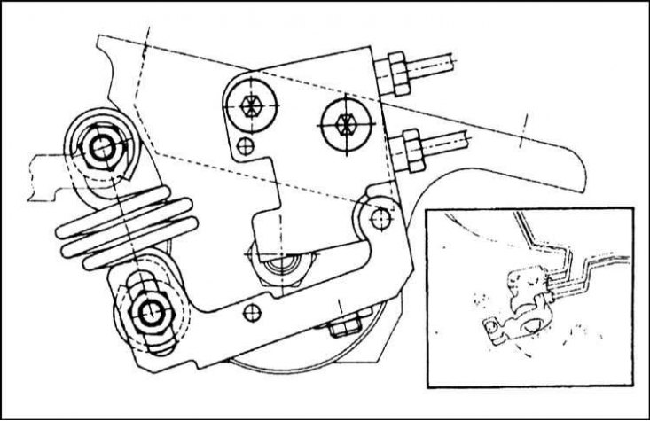
The regulator adjusts the pressure in the hydraulic circuits of the vehicle's rear wheel brakes depending on the load and position of the body.
During routine maintenance of the vehicle, attention should be paid to the tightness of the connections of the control valve and the freedom of movement of its drive components should be checked. If defects are detected, the control valve should be replaced as an assembly. The correct functioning of the control valve should be checked at a service station.
Brake fluid reservoir
The two-chamber brake fluid reservoir is made of translucent plastic, which allows visual monitoring of the fluid level in it. The reservoir connecting pipes are inserted into the input sockets of the master cylinder equipped with sealing bushings.
Article source: this website: skodabook
The tank is divided internally by a partition into two independent chambers. The partition does not reach the top cover of the tank, which allows adding liquid to both chambers at once. The circuits are separated only after the liquid level drops below the edge of the partition.
The filler neck of the reservoir is closed with a screw cap, in which, along with the system of channels connecting the internal cavity with the atmosphere, the terminals of the brake fluid level sensor-switch and the sensor-switch itself are mounted (see Chapter On-board electrical equipment).
The tank body has marks for the minimum and maximum liquid levels.
Vacuum brake booster
This device is designed to increase the force applied by the driver to the foot brake pedal in order to improve braking efficiency.
The vacuum booster servo unit housing consists of two parts: the housing itself (5) and the cover (1). The tightness of both parts of the assembly is ensured by the fit of the edges of the diaphragm (3), clamped in the housing groove. The central part of the diaphragm is hermetically seated in the piston groove (2) and divides the internal space of the assembly into two chambers. The spring (10) ensures the return of the rod (7) together with the diaphragm to the initial position.
The piston is mechanically connected to the pusher rod (7). An adjusting tip (8) is screwed onto the end of the rod, with the help of which the installation clearance between the master cylinder piston and the pusher is adjusted (see section Removal, checking the condition and installing the brake booster check valve with a hose).
The tightness of the pusher fit in the assembly is ensured by a rubber gasket (6).
Inside the piston assembly there is a valve (12), against which the spherical end of the control pusher (15) rests. The pusher is connected to the foot brake pedal.
In the front part of the valve (12) there is a seat of a special shape, which is covered, in turn, by the valve (13). The front (vacuum) chamber (4) is connected by a channel (17) to the piston with the rear (atmospheric) chamber (11) located behind the piston.
The filter (16), duplicating the role of the rubber protective cover (14), prevents dust from entering the assembly when atmospheric air is sucked in.
When the foot brake pedal is depressed, the control pusher moves the first piston valve, which closes the channel connecting the vacuum chamber with the atmospheric chamber and opens access to the latter for outside air. The vacuum in the vacuum chamber with the engine running is created due to the presence of a connection with the intake manifold. Due to the pressure difference on different sides of the piston, the latter shifts to the left, compressing the spring and resting the pusher rod against the master cylinder piston.
When the foot brake pedal is pressed hard, the vacuum booster piston moves to the left a considerable distance. At the same time, the volume of the atmospheric chamber increases somewhat and outside air is sucked into the cavity.
After releasing the pedal, the valve (4) ensures equalization of pressure on both sides of the piston, and the spring returns the diaphragm to its original state, also causing a reverse displacement of the pusher rod and, accordingly, the first piston of the master cylinder.
The vacuum supply to the front chamber of the servo drive is carried out through a one-way valve included in the line connecting the block to the engine intake manifold. The valve prevents air and fuel vapors from entering the vacuum chamber of the servo drive when the engine is turned off. Thanks to this valve, the first braking with a stalled engine occurs with the vacuum booster working (after releasing the pedal, the vacuum booster stops functioning).
As follows from the above description of the operating principle of the servo drive, brake boosting becomes possible only when the engine is running, when a vacuum is maintained in the intake manifold of the latter.
To stop a towed or coasting vehicle with a stalled engine, apply slightly more force than usual to the foot brake pedal.
Spare parts for the brake booster servo drive are not supplied, and therefore, in case of failure, the unit must be replaced as an assembly. A description of the procedures for removing and installing the servo drive assembly is given in Section Checking the proper functioning, removing and installing the brake booster. The block mounting dimensions are shown in the illustration.
Front wheel brakes
The main components of the front wheel brake mechanism are the brake disc and the caliper assembly with brake pads.
The brake disc is cast from grey cast iron and is attached to the wheel hub flange with one M6x14 bolt. The inner side of the disc is protected from dirt by a special casing.
The main body of the brake caliper contains a piston. Two pads equipped with friction linings are inserted into the anchor bracket.
The caliper body is attached to the anchor bracket by means of one (girgling original equipment mechanisms) or two bolts (mechanisms of licensed assembly). In any case, the bolts are screwed into the holes in the ends of the guide pins. The body can then move freely along the guide pins.
The caliper guide pins are coated with a thin layer of silicone grease and protected from dirt by rubber dust boots. The anchor bracket is equipped with mounting seats for installing brake pads and two threaded holes for bolts, with the help of which the entire assembly is attached to the steering knuckle of the wheel hub assembly.
Inside the caliper body there is a hydraulic cylinder with a piston. The tightness of the piston fit in the cylinder is ensured by a sealing cuff.
The pads consist of a metal plate with a friction lining glued to one side. The pad is held in the seat by a spring attached to the plate. At the same time, the spring serves to eliminate pad vibrations.
When the foot brake pedal is depressed, the hydraulic fluid acts on the caliper piston, causing the pads to be pressed against the working surface of the disc. The movement of the piston leads to deformation of the cuff. After the pedal is released, the brake fluid pressure drops and, due to the spring properties of the cuff, the piston moves back, returning to the cylinder. As a result of cuff wear, a moment may come when the piston stops being drawn into the cylinder after the pedal is released. In this case, the pads will remain pressed against the brake disc and the mechanism begins to overheat.
It should be noted that as the friction linings of the pads are triggered, the piston gradually moves out of the cylinder. At the same time, the caliper body moves along the guide pins, automatically compensating for wear.
Rear wheel brakes
The design of the drum brake mechanism of the rear wheels is shown in the illustrations.
The stamped steel brake shield is attached to the rear suspension arm. Brake shoe brackets are riveted to the bottom of the shield.
The shoes have a T-shaped cross-section and their upper end rests against the piston pushers of the wheel cylinder, and their lower end rests against a bracket fixed to the brake shield. Friction linings are glued to the convex side of the shoes with special glue.
The rear shoes of the right and left brake mechanisms have the same design, while the front ones are not interchangeable due to the presence of asymmetrically located axles in the lower part for installing automatic adjustment locks for working clearances.
The shoes are connected to each other by two tension springs - upper and lower. The springs have different lengths and ensure that the ends of the shoes fit both to the piston pushers of the wheel cylinder and to the axles.
An anchor pin is threaded through a hole in the central part of the shoes and secured with a cotter pin. The pin fixes the shoe in the axial direction relative to the brake shield.
The wheel cylinder is cast from cast iron. The cylinder is mounted on the brake mechanism shield with a mounting flange using two M6x10 bolts. The flange also has a hole for the bleed valve.
Two pistons equipped with rubber sealing cuffs are installed inside the cylinder. The internal spring ensures constant pressure of the piston pushers against the brake shoes. The piston pushers have a special shape and are placed on the upper edges of the shoes with a groove provided in the outer end. The wheel cylinder is protected on both sides by rubber dust boots, preventing contaminants from getting inside the assembly.
The brake drum is cast from cast iron. There are ten holes in the front wall of the drum (not counting the central one). Two holes are intended for fastening the drum to the flange of the hub assembly using M8x16 bolts, four are for fastening to the wheel disk assembly, two more are auxiliary and are used when removing the drum, and the remaining two provide access for checking the return stroke of the automatic clearance adjuster lever between the shoes and the drum.
When the foot brake pedal is depressed, the brake fluid inside the wheel cylinder causes the piston assemblies to move apart, whose pushers move the upper edges of the shoes apart, pressing the latter with friction linings to the working surface of the drum. After releasing the pedal, the shoes return to their original position due to the force developed by the tension springs.
Excessive clearance between the shoes and the working surface of the drum leads to an increase in the free travel of the foot brake pedal and, accordingly, to a delay in the operation of the brake mechanisms. In view of the above, the said clearance should be reduced to a minimum. For this purpose, the brake mechanisms are equipped with an automatic clearance adjustment device, thanks to which the controlled distance is constantly maintained within 0.4÷0.6 mm.
The expansion bar is an integral part of the automatic gap adjuster mechanism. Other components of the device include a locking device with a spiral spring installed at the bottom of the front shoe, as well as a spring stretched between the bar and a special hole in the rear shoe.
The size of the gap between the friction linings of the shoes and the working surface of the drum depends on the size of the gap between the teeth on the lower part of the adjusting lever and the teeth on the upper part of the retainer.