Note.
- Necessary special devices, control and measuring devices, as well as auxiliary means:
- Assembly tool -710417/1-.
- Counterholder -T30004 (3415) -.
- Pin -T30004/2 (3415/2) -.
- Gasket Stripper Seal Remover (storage code GST item #R 34402), manufacturer Retech s.r.o.
- Cleaning and degreasing agent, e.g. -0 000 401 04-.
- Protective gloves and goggles.
- Sealing agent -D 176 600A1-.
Removing
1. Remove the lower protective casing of the engine compartment.
2. Remove the fender liner of the right front wheel arch (for details, see the relevant section in chapter Body).
3. Remove the V-ribbed implement drive belt (more. see relevant section in this chapter).
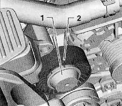
4. Remove, if present, the dust cap (1), shown in the figure below.
5. Remove guide roller (2), attachment drive belt as shown in the figure below.
6. Remove coolant pump pulley by holding pulley with water pump wrench -VAG1590-.
7. Remove the pulley on the crankshaft.
8. Remove the engine oil pan assembly.
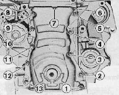
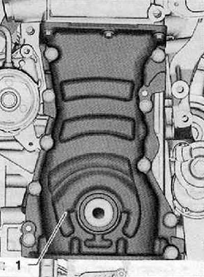
9. Unscrew all the fixing screws of the bottom cover of the timing chain drive (1), as shown in the figure below.
10. Disconnect and carefully remove the timing chain cover.
Installation
1. Installation is carried out in the reverse order of operations, and the following instructions must be observed.
Attention. Protective gloves and goggles should be used when working with seal remover and degreaser.
2. Eliminate residual sealant (sealant) from the sealing surfaces on the lower timing chain cover and on the cylinder block with a chemical seal remover.
3. Degrease the sealing surfaces.
4. Cut off the tip with scissors (jet) tube on the front mark (∅ jet - approx. 3 mm).
Note.
- Installation must not last longer than 6 minutes from the moment the sealing agent is applied to the tightening of the fixing screws with a torque of 5 Nm - turning 30°.
- The sealant begins to harden after 6 minutes. Apply new mounting bolts.
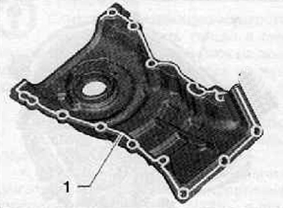
5. Apply sealant/sealant -D 176 600 A1- to the sealing surface (1), shown in the figure below.
6. The layer of sealing agent should be 2...3 mm thick, and in the places where the holes for the screws are located, it must be applied around the holes.
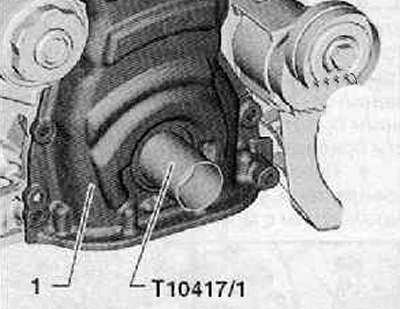
7. Push assembly tool -T10417/1- onto crankshaft journal.
8. Install the lower timing chain cover (1) together with the O-ring carefully onto the mounting tool as shown in the figure below.
9. Remove the assembly tool from the crankshaft journal.
10. Install the lower timing chain cover onto the dowel pins (arrows) until it rests against the cylinder block as shown in the figure below. Make sure the timing chain cover is not jammed.
Attention. Observe the tightening torque of the fixing screws! New screws must be used for installation.
11. New timing chain housing mounting screws must first be tightened evenly by hand.
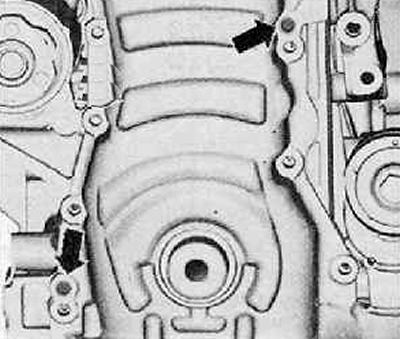
12. Tighten the mounting screws in the specified sequence from 1 to 12, as shown in the figure below. Tightening torque: 5 Nm + turn an additional 30°.
13. Install the crankshaft pulley.
Tightening torques:
- water pump pulley: 20 Nm.
- guide roller: 40 Nm.