
Removing
1. Remove the lower protective casing of the engine compartment.
2. Drain the coolant into a prepared container.
3. Remove the fender liner of the right front wheel arch (for details, see the relevant section in chapter Body).
4. Remove the V-ribbed implement drive belt (more, see relevant section in this chapter).
5. Remove the top timing chain cover (more, see relevant section in this chapter).
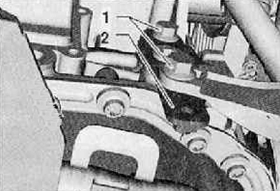
6. Remove fixing screws (1), remove the coolant pipe holder (2), as shown in the figure below.
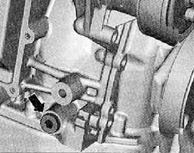
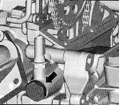
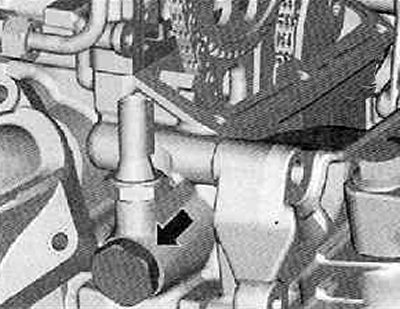
7. Unscrew the screw plug (arrow) on the cylinder block as shown in the figure below.
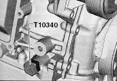
8. Screw the locking screw -T10340- into the cylinder block as far as it will go, as shown in the figure below.
Attention.
- If the locking screw -T10340- cannot be screwed in as far as it will go, the crankshaft is not in the correct position.
- In this case, proceed according to the following method.
9. Unscrew the locking screw.
10. Rotate the crankshaft 90° (¼ turn) in the direction of rotation of the motor shaft.
11. Screw locking screw -T10340- into cylinder block as far as it will go.
12. Locking screw -T10340- must be tightened with a tightening torque of 30 Nm.
13. Turn the crankshaft to the stop in the direction of rotation of the engine shaft.
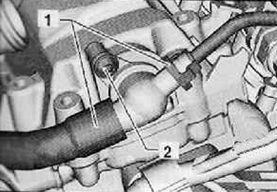
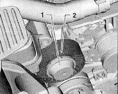
14. Disconnect both coolant hoses (1) from the check valve as shown in the figure below.
15. Unscrew the fixing screw (2), remove the check valve from the cylinder head cover as shown in the figure below.
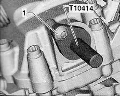
16. Install locking bolt -T10414- as far as it will go in the cylinder head cover.
17. Finger tighten the fixing screw shown in the figure below.
18. Remove the oil pan assembly.
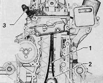
19. Remove, if present, the dust cap (1), shown in the figure below.
20. Unscrew the fastening bolt and remove the guide roller (2), as shown in the figure below.
21. Remove the mounting bolts and remove the water pump drive pulley. When unscrewing the mounting bolts, keep the pulley from turning with a special tool (V.A.G 1590).
22. Remove the mounting bolt and remove the crankshaft pulley.
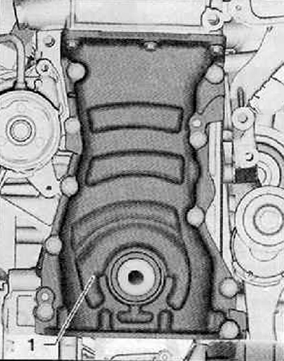
23. After loosening all the fixing screws of the timing chain cover (1), remove it carefully as shown in the figure below.
24. Unscrew the tensioner (arrow) camshaft drive chain as shown in the figure below.
25. Mark the direction of movement of the camshaft drive chain with a felt-tip pen.
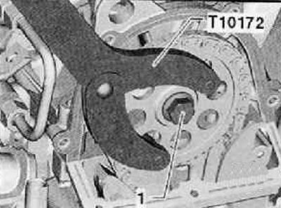
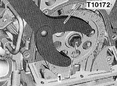
26. Hold the camshaft sprocket with counterholder -T10172- and loosen the securing bolt (1) camshaft drive gear as shown in the figure below.
27. Remove the camshaft drive gear along with the mounting bolt.
28. Remove the camshaft drive chain downwards.
Installation
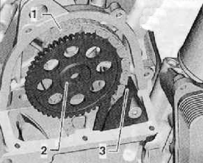
1. Install the camshaft drive chain (1) from below to the front sprocket of the crankshaft (2), guide it upwards between the guide rack and the tensioner rack, as shown in the figure below.
2. Fix the camshaft drive chain with a screwdriver (3) from falling off, as shown in the figure below.
3. Put on the camshaft drive chain (1) on the chain sprocket (2), as shown in the figure below.
4. On the section of the guide rail (3) The camshaft drive chain must fit and be slightly tensioned.
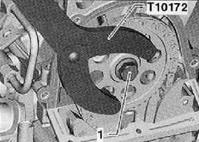
5. Hold the camshaft sprocket with counterholder -T10172- and tighten the securing bolt (1) camshaft drive gear with a tightening torque of 50 Nm as shown in the figure below.
Note. The fastening bolt must be rotated 90° (¼ turn) only after checking the distribution of the valve timing at the end of the workflow.
6. Tighten the chain tensioner (arrow) with a tightening torque of 60 Nm as shown in the figure below.
7. Remove retaining bolt -T10414- from camshaft.
8. Remove locking screw -T10340- from cylinder block.
9. Turn the crankshaft two turns in the direction of rotation of the engine shaft.
10. Check the valve timing over time.
If the time distribution is normal
11. Hold the camshaft sprocket with counterholder -T10172- and turn the securing bolt (1) at 90° (¼ turn), as shown in the figure below.
12. Install the bottom timing chain cover.
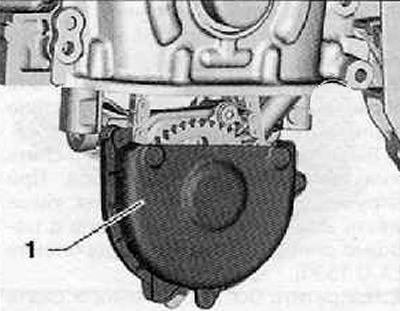
13. Install cover (1) oil pump drive chain as shown in the figure below.
14. Install the oil pan.
15. Install the crankshaft pulley.
16. Install the poly V-belt for the attachment drive (more, see relevant section in this chapter).
17. Install the top timing chain cover (more, see relevant section in this chapter).
18. Fill the cooling system with coolant.
19. Further installation is carried out in the reverse order of removal.