



Removing
Note. Do not start dismantling the cylinder head until the engine has cooled below 35°C. Otherwise, the cylinder head may be damaged. Remove all pistons from TDC.
1. Drain all coolant from the cooling system into a container prepared in advance.
2. Remove the thermostat housing from the cylinder head.
3. Remove the top timing chain cover (more, see relevant section in this chapter).
4. Remove the bottom timing chain cover (more, see relevant section in this chapter).
5. Remove the top attachment mounting bracket.
6. Remove turbocharger assembly with exhaust manifold (for more details, see the relevant section in chapter Intake and exhaust system).
7. Remove intake manifold assembly (for details, see the relevant section in chapter Intake and exhaust system).
8. Remove the expansion tank of the engine cooling system.
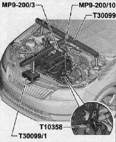
9. Install a special device for hanging the power unit (Т30099) assembled with bracket MP9-200/3 above the engine compartment, as shown in the figure below.
10. Unscrew the bolt securing the gearbox to the engine, in its place screw in the bolt securing the mounting bracket T10358.
11. Using the MP9-200/3 spindle, slightly hang out the power unit assembly.
12. Disconnect the fuel lines (3) And (4). shown in the figure below. To do this, press the unlock buttons.
Attention. The fuel supply line is under pressure. To prevent injury, wear protective goggles and protective gloves. Before proceeding with the opening of the system, it is necessary to cover the junction with a clean rag.
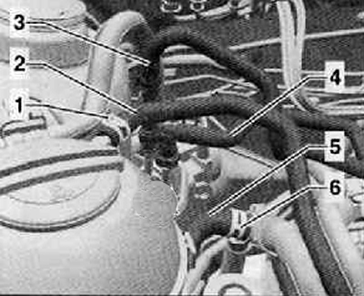
13. Unscrew the fastening nut (1). disconnect the ground wire from the engine mount (frame) (2), shown in the figure below.
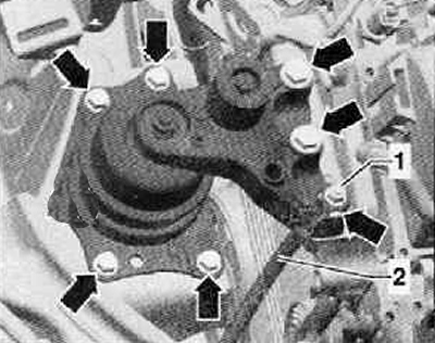
14. Unscrew the fastening bolts (arrows), remove the engine mount.
15. Remove the cylinder head cover (more, see relevant section in this chapter).
16. Remove the tensioner and guide rails of the camshaft drive chain.
17. Remove the rocker arms together with the hydraulic pushers, put them on a clean base.
18. Do not dismantle rocker arms and hydraulic compensators.
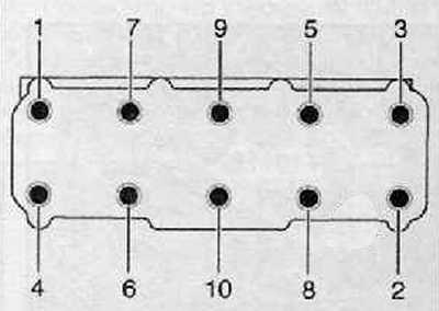
19. Unscrew the bolts of the cylinder head in the prescribed sequence shown in the figure below.
20. Carefully remove the cylinder head assembly.
Installation
Note. Check valve tightening torque (arrow), shown in the figure below: 7 Nm.
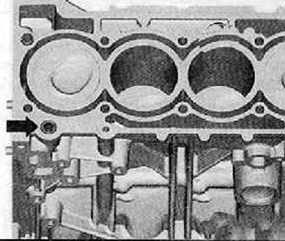
Note. It is impossible for any of the pistons to be at TDC.
Note.
- A new cylinder head gasket should only be removed from the packaging just before installation.
- A new gasket must be handled with extra care. Damage is the cause of leakage.
- The cylinder head bolt holes must not contain any amount of oil or coolant.
1. Seal the cylinders with clean rags to prevent any dirt from getting into the space between the cylinder walls and the pistons.
Attention. Protective gloves and goggles should be used when working with seal remover and degreaser.
2. Make sure that no dirt gets into the cylinders or into the lubrication and coolant channels when cleaning the cylinder head and block.
3. Carefully remove the remnants of the old gasket from the cylinder head and from the cylinder block with a chemical seal remover.
4. Set the piston of the 1st cylinder to TDC, turn the crankshaft back a little.
5. Install a new cylinder head gasket. Inscription (part number) should be directed upwards.
6. Install the cylinder head assembly on the cylinder block. In this case, the centering pins in the cylinder block should be guided.
7. Install new cylinder head bolts, tighten by hand.
8. Bolts of fastening of a head of the block of cylinders should be tightened in the sequence presented in drawing below as follows:
- All bolts must be tightened with a tightening torque of 40 Nm.
- Then turn all the bolts additionally with a socket wrench by 90° (¼ turn).
- Then turn all screws 90°again (¼ turn).
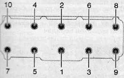
9. Install the hydraulic compensators in the cylinder head and put on the rocker arms corresponding to them on the ends of the valve stems.
10. Install cylinder head cover (more, see relevant section in this chapter).
11. Adjust the valve timing in time (more, see relevant section in this chapter).
12. Further installation is carried out in the reverse order of removal.
13. Fill the cooling system with coolant, then remove air from the system.