
Note.
- Necessary special devices, control measuring devices, as well as auxiliary means:
- Retaining bolt -710414-.
- Locking screw -T10340-.
- Controller -T10172 -.
1. Drain the coolant into a prepared container.
2. Remove the upper timing chain cover.
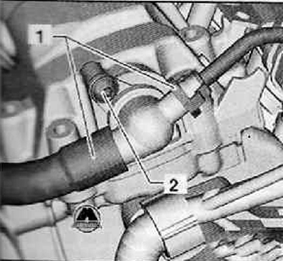
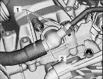
3. Disconnect both coolant hoses (1) from the check valve shown in the figure below.
4. Unscrew the fixing screw (2), remove the check valve from the cylinder head cover as shown in the figure below.
Vehicles with independent auxiliary heater
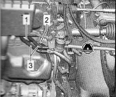
5. tighten the fastening screws (1) And (2) coolant pipe holders for independent auxiliary heater (3), as shown in the figure below.
Continuation for all cars
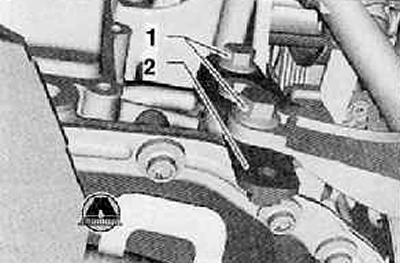
6. Unscrew the fastening screws (1) and remove the coolant tube holder (2), as shown in the figure below.
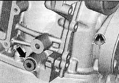
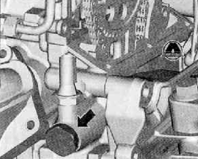
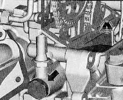
7. Unscrew the screw plug (arrow) on the cylinder block shown in the figure below.
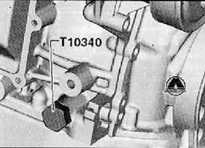
8. Screw special locking screw -T10340- into cylinder block as far as it will go.
Attention.
- If the locking screw -T10340- cannot be screwed in as far as it will go, the crankshaft is not in the correct position!
- In this case, proceed according to the following method.
9. Unscrew the locking screw.
10. Rotate the crankshaft 90° (¼ turn) in the direction of rotation of the motor shaft.
11. Screw locking screw -T10340- into cylinder block as far as it will go.
12. Locking screw -T10340- must be tightened to 30 Nm.
13. Turn the crankshaft to the stop in the direction of rotation of the engine shaft.
14. Use locking screw -T10340- to block crankshaft in direction of rotation of engine shaft.
15. Remove the engine oil pan.
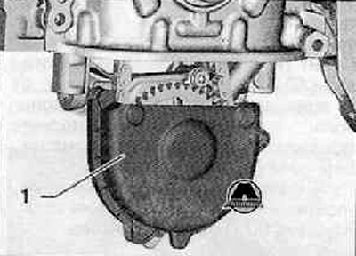
16.Remove the cover (1) oil pump drive chain as shown in the figure below.
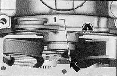
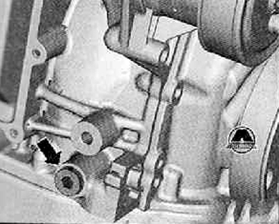
17. Unscrew the tensioner (arrow) camshaft drive chain as shown in the figure below.
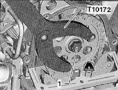
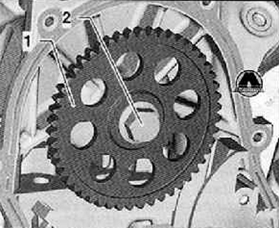
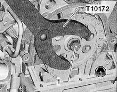
18. Hold the camshaft sprocket with counterholder -T10172- and loosen the fixing screw (1) camshaft drive gear as shown in the figure below.
19. Remove the camshaft drive gear together with the fixing screw.
20. Put the camshaft drive chain (1) at high tide (arrow) timing chain cover as shown in the figure below.
Note. A lug on the inside of the timing chain housing prevents the camshaft timing chain from falling off.
21. Installing the camshaft drive gear (1) on the camshaft, tighten the fixing screw (2) with a tightening torque of 50 Nm.
22. While tightening, hold the camshaft sprocket with counterholder -T10172-.
23. Then you should turn the crankshaft against the direction of rotation of the engine shaft by 90° (¼ turn) back.
Note. By turning the crankshaft against the direction of rotation of the engine shaft, damage to the valves is prevented during the subsequent adjustment of the camshaft.
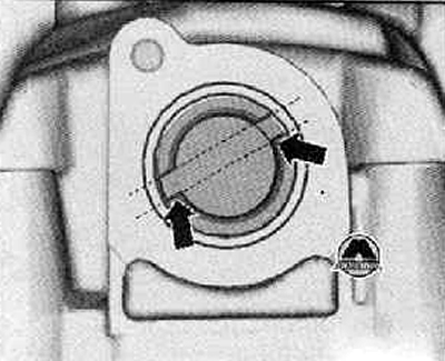
24. Turn the camshaft until the splines (arrows) will not be in the presented position, as shown in the figure below.
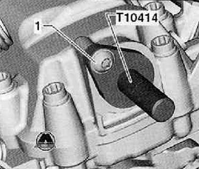
25. Install retaining bolt -T10414- as far as it will go in the cylinder head cover.
26. Tighten the fixing screw by hand (1), shown in the figure below.
27. Turn the crankshaft to the stop in the direction of rotation of the engine shaft.
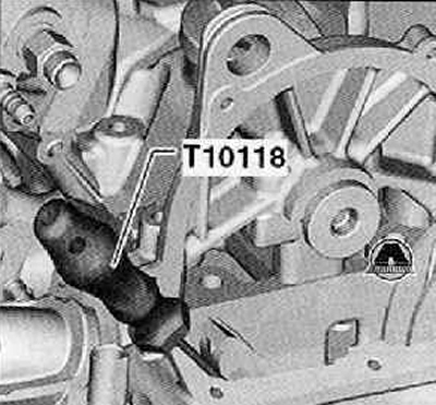
28. Lift up the camshaft timing chain using assembly tool -T10118- as shown in the figure below.
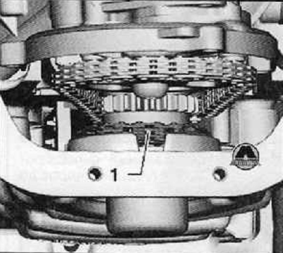
29. Check the correct position of the camshaft drive chain from below (1) on the crankshaft sprocket as shown in the figure below.
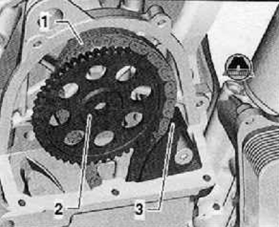
30. Put on the camshaft drive chain (1) on the chain sprocket (2), as shown in the figure below.
31. On the section of the guide bar (3) The camshaft drive chain must be in contact and slightly tensioned.
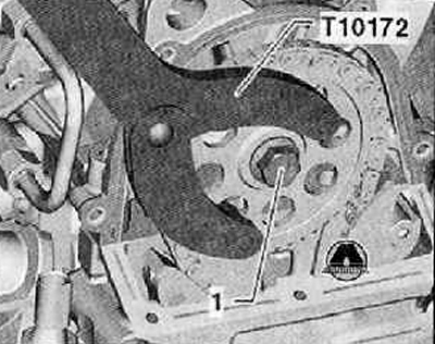
32.Hold the camshaft sprocket with counterholder -T10172- and tighten the fixing screw (1) camshaft drive gear with a tightening torque of 50 Nm as shown in the figure below.
Note. The fixing screw must be turned by 90° (¼ turn) only after checking the distribution of the valve timing at the end of the workflow.
33. Having installed the chain tensioner, tighten it with a tightening torque of 60 Nm.
34. Remove retaining bolt -T10414- from camshaft.
35. Remove locking screw -T10340- from cylinder block.
36. Turn the crankshaft two turns in the direction of rotation of the engine shaft.
37. Screw locking screw -T10340- into cylinder block as far as it will go.
Z8. Turn the crankshaft to the stop in the direction of rotation of the engine shaft
39. Valve timing is OK if the locking bolt -T10414- can be installed on the camshaft. In the event that the distribution in time is not normal, the valve timing adjustment should be repeated.
40. Hold the camshaft sprocket with counterholder -T10172- and turn the fixing screw (1) at 90° (¼ turn), as shown in the figure below.
41. Remove locking pin -T10414- and locking screw -T10340-.
42. Install the top timing chain cover.
43. Install a check valve. Mounting screw tightening torque (2): 8 Nm.
44. Connect the hoses shown in the figure below (1).
45. Install the oil pan.
46. Install and tighten the screw plug to the required tightening torque. Tightening torque: 30 Nm.
47. Fill the engine cooling system with coolant.
48. Further, installation is carried out in the reverse order of removal.