



Contents: Removal ⬇ Installation ⬇
Removal
Attention.
- When performing any assembly work, especially in the engine compartment due to the narrow assembly area, the following instructions must be observed:
- Any kind of pipelines (for example, for fuel, hydraulic system, cooling device, brake fluid, vacuum lines) and electrical wires should be laid in such a way as to restore their original condition.
- Ensure that there is sufficient space between the pipeline and moving or hot components to avoid damage to the pipeline.
1. With the ignition off, disconnect the negative terminal from the battery.
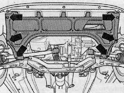
2. Remove the lower engine compartment protective cover (arrows) as shown in the figure below.
3. Unscrew the mounting bolts and disconnect the right and left drive shafts from the gearbox (for more details, see the corresponding section in the chapter Drive shafts).
4. Raise the drive shafts and tie them using a suitable piece of wire.
5. Remove the front part of the exhaust pipe (for more details, see the relevant section in the chapter Intake and exhaust system).
6. Drain the coolant into a previously prepared container.
7. Remove the battery and battery holder (for details, see the relevant section in the chapter Engine electrical equipment).
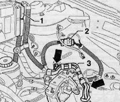
8. Disconnect the wiring harness connector (1) from the engine control unit as shown in the figure below.
9. Disconnect the wiring harness connector (2) shown in the figure below.
10. Release the wire holder (3) (arrows) from the fixed position, as shown in the figure below.
11. Disconnect all wires from the engine, gearbox, starter and radiator that would interfere with removal.
12. Remove the suction hose from the brake booster.
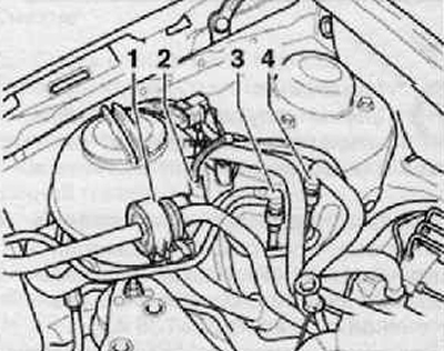
13. Press the locking buttons to disconnect the fuel supply (4) and drain (3) pipes of the fuel system, as shown in the figure below.
14. Disconnect the wiring harness connector (2), then disconnect and remove the activated carbon canister solenoid valve, fuel vapor recovery system (1), as shown in the figure below.
15. Remove the cooling system bleed hose from the front coolant pipe.
16. Remove the cooling system water hose from the branch pipe under the cooling system expansion tank.
17. Remove the flexible shaft counter support (bowden cables).
18. Remove the hydraulic clutch release drive slave cylinder (for more details, see the corresponding section in the chapter Manual transmission).
19. Disconnect the coolant hoses at the top and bottom - at the connecting pipes from the radiator.
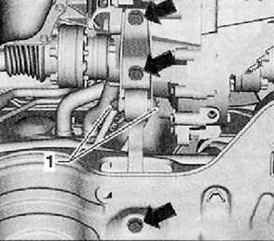
20. Unscrew the mounting bolts (arrows) and remove the power unit rocker support.
For cars with air conditioning
Caution: Do not open the refrigerant circuit of the air conditioning system.
21. Remove the poly V-belt of the accessory drive (for more details, see the relevant section in this chapter).
22. Disconnect the wiring harness connector from the air conditioning compressor.
23. Remove the air conditioning compressor with the pipeline attached.
24. Suspend the air conditioning compressor from the vehicle in such a way that no collision occurs during removal of the unit from the vehicle.
Note: Do not bend the air conditioning system hoses connected to the compressor.
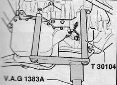
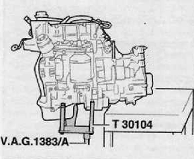
25. Install the engine support bracket "T30104" in a device for removing and installing the power unit, for example "VAG 1383/A".
26. Connect the engine support bracket "T30104" with lock nuts and M8 screws, applying a tightening torque of 30 Nm to the cylinder block.
Note.
- Check that all hose and proxy connections are disconnected:; between the engine, gearbox and body and, if necessary, separate them.
- To remove the fastening bolts, use the "VAS 5085" step ladder.
27. Slightly raise the engine with gearbox using a device for removing and installing the power unit, e.g. "VA G 1383/A".
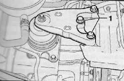
28. Unscrew the fastening screws (1) shown in the figure below.
For vehicles with other types of support
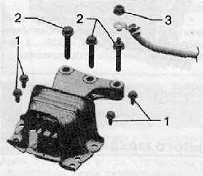
29. Loosen the fastening nut (3) and disconnect the ground wire from the bracket, shown in the figure below.
30. Unscrew the bolts securing the bracket to the power unit support (2), as shown in the figure below.
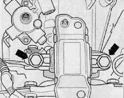
31. Unscrew the mounting screws (arrows) from the gearbox bearing.
32. Lower the engine with the gearbox down.
Note: When lowering the engine with the gearbox, you need to be careful. It is necessary that there is always enough space in the surrounding area.
Securing the engine on the assembly stand
33. Place the engine and gearbox using the removal and installation device on the storage table.
34. Lower the engine with the gearbox so that the gearbox lies on the table top.
35. Unscrew the bolts connecting the engine and gearbox.
36. Disconnect the gearbox from the engine.
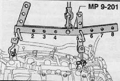
37. Having hooked the suspension device (MP9-201 (2024 A)) in the manner indicated below, lift it from the power unit support using a shop crane.
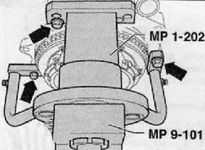
38. To carry out assembly work, it is necessary to secure the engine with a device for removing and installing the engine and gearbox (MP1 202) (using 3 bolts (arrows)) on the assembly stand "MP9-101", as shown in the figure below.
Installation
1. Installation is performed in the reverse order of removal. Observe the following instructions:
- Check the presence of 2 centering bushings in the cylinder block for centering the gearbox; if necessary, insert them.
- If necessary, check the correct centering of the clutch disc.
- Check the wear of the clutch release bearing and, if necessary, replace the bearing.
- The splined connection on the drive shaft should be lubricated with "G 000 100" grease.
- When assembling the engine-gearbox unit, care must be taken to ensure that there is sufficient free space left in relation to the other parts.
- Center the engine with the gearbox so that there is no internal stress.
- Install the hydraulic clutch release cylinder (for more details, see the relevant section in the chapter Manual transmission).
- Connect the shift drive and adjust the Bowden cables to shift gears.
For cars with air conditioning
- Install the air conditioning compressor (for more details, see the relevant section in the chapter Heating, ventilation and air conditioning system).
- Install the poly V-belt for the accessory drive (more details, see the relevant section in this chapter).
Continued for all cars
- Connect the right and left drive shafts to the gearbox.
- Install the front section of the exhaust pipe, align the exhaust system without internal stress.
- Connect the coolant hoses.
Note: Drained coolant can only be used if the engine block, cylinder head, radiator or heat exchanger have not been replaced.
- Pour in coolant.
- Before starting the engine, you should check the oil level.
- Adapt the engine control unit to the throttle control mechanism "J338" using special equipment.
Note.
- Before installation, lubricate all bearings and working surfaces with oil.
- If, during engine repair, an increased amount of metal shavings or worn-out particles of material appear, this may indicate damage to the crankshaft main bearings or connecting rod bearings. To prevent subsequent damage, the following work must be performed after repair.
- Clean the lubrication channels thoroughly.
- Replace oil injection nozzles.
- Replace the oil cooler.
- Replace the oil filter.