Note. The sealing surfaces of the cylinder head cover must not be machined.
Removing
1. Remove the timing chain housing.
2. Remove the camshaft chain sprockets (more. see relevant section in this chapter).
3. Remove locking device -T10123-.
4. Remove ignition coils with power output stage -N70-, -N127-, -N291- using special puller -T10094A-.
5. After loosening the bolts of the cylinder head cover from the outside to the inside, remove them.
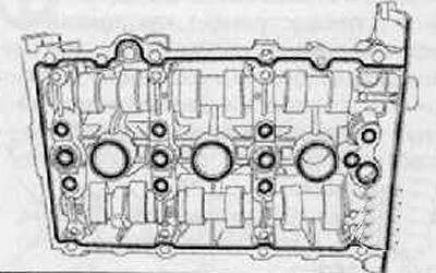
6. Carefully remove the cylinder head cover by lightly tapping it, if necessary, with a rubber mallet in an upward direction (cylinder head cover sits on dowel pins).
Attention. Protective gloves and goggles should be used when working with seal remover and degreaser.
7. Remove seal residues on cylinder head and cylinder head cover with seal remover.
Note. It is impossible for sealant residues to remain in the cylinder head.
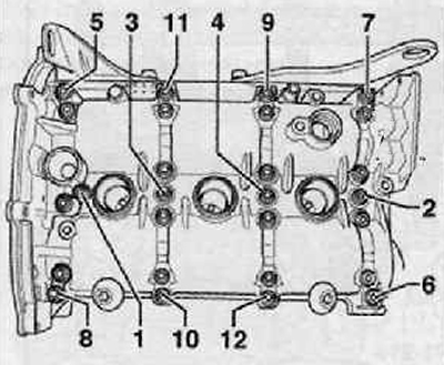
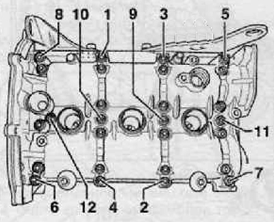
8. Loosen and remove the screws for installing the camshafts in the specified sequence.
9. Carefully remove the camshaft bearing caps.
10. Carefully remove the camshafts in an upward direction and lay them down on a clean base.
Installation
Note. The lug of the intake camshaft must be at the bore for the Hall sensor.
1. Lubricate the camshaft bearings on the cylinder head cover and on the camshaft covers with a continuous coat of grease (G 052 735 A2).
2. Carefully insert the camshafts into the cylinder head cover.
3. Install the camshaft bearing caps.
4. Insert the screws for installing the camshafts in the specified sequence and tighten them by hand.
5. Make sure that the camshaft bearing caps are not jammed. Tightening torque: 10 Nm + tighten an additional 90° (¼ turn).
6. Check and make sure that the camshafts rotate easily in their bearings.
Note
- Check and make sure that there are no fuels and lubricants on the mating surface of the cylinder head cover.
- Avoid any of the pistons being at top dead center. While turning the camshaft, the valves can hit the piston at TDC.
7. Cut off the sealant jet with scissors (sealant) (AMV 174 004 01) at the front mark (∅ jet - no more than 2 mm).
8. Apply the sealant in an even, thin layer to the clean sealing surfaces of the cylinder head. The thickness of the sealant roller should be 2-3 mm. In the places where the bolt holes are located, a sealing agent must be applied on the inside.
Note.
- The thickness of the sealant track must not exceed 3 mm, as in this case, excess sealant will enter the lubrication channels and may cause engine damage.
- The cylinder head cover must be installed within 15 minutes of applying the sealant.
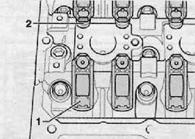
8. Make sure that all the rocker arms fit correctly on the ends of the valve stems (1) and to the corresponding hydraulic compensators (2), as shown in the figure below.
9. Carefully install the cylinder head cover perpendicularly from above on the dowel pins (arrows) in the cylinder head as shown in the figure below.

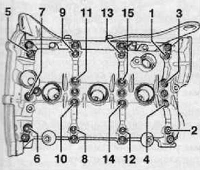
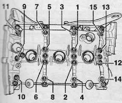
10. Install new mounting bolts, and tighten them evenly crosswise from the inside of the cover to the outside. Make sure that the cylinder head cover is not twisted during installation Tightening torque of the mounting bolts: 10 Nm + turn an additional 90° (¼ turn).
11. Remove the sealant that has squeezed out, especially in the area of the housing of the timing chain drive.
Note. After installing the cylinder head cover, the seal must dry for approx. 30 minutes.
12. Further installation is carried out in the reverse order of removal.