
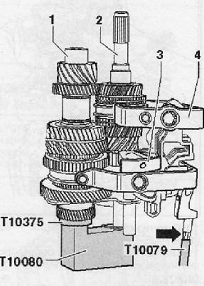
1. Install the input shaft assembly (2), output shaft (1) together with the bearing support into a special tool (Т10080), as shown in the figure below.
2. Insert the shift forks (4) on the fork stems as shown in the figure below.
3. Install the shaft together with the reverse gear (3).
4. Screw in the guide bolts of the special tool (Т10079) into the reverse gear shaft mounting bolts (arrow), as shown in the figure below.
5th gear not installed on transmission output shaft
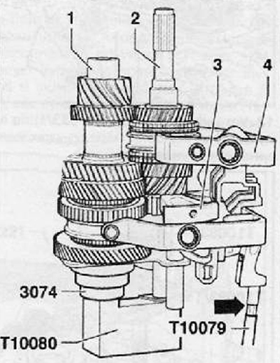
5. Install Lead (2) and slave (1) shafts assembled with bearing support in a special tool (Т10080), as shown in the figure below.
6. Install the shift forks (4) on the fork stems as shown in the figure below.
7. Install reverse gear shaft (3) along with the gear.
8. Screw on the guide bolts (Т10079) on the bolts of the reverse gear (arrows), as shown in the figure below.
Continuation for all cars
9. Install the components in the gearbox housing by passing the guide bolt (Т10079) through the holes of the selector and engagement mechanism retainers in the gearbox housing, as shown in the figure below.
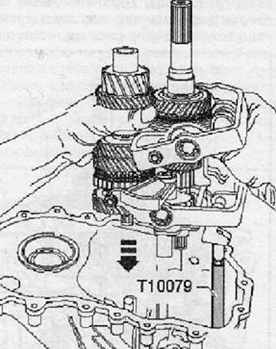
10. Twist the guide bolt (Т10079).
11. Before pressing on the gearbox shaft bearing support, check:
Correct installation of gear shift forks. Make sure they move freely on the stem bushings.
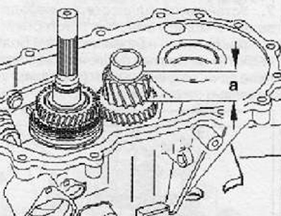
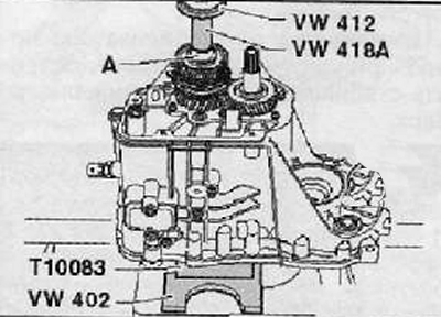
Measure gear length «A», shown in the figure below.
Note.
- The output shafts of different gearboxes can have different values «A».
- The length -a- must be 30.6 mm.
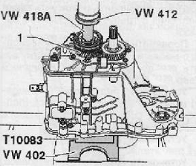
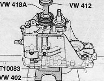
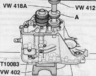
12. Install washer (Т10083/1) on the gearbox input shaft, as shown in the figure below.
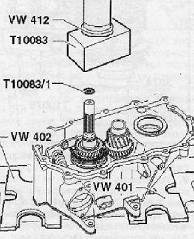
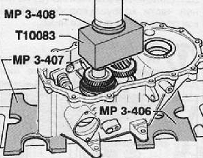
13. Carefully press the bearing pedestal together with the drive and driven shaft as shown in the figure below.
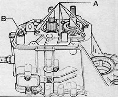
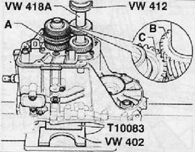
14. Tighten the mounting bolt (A) reverse gear shaft shown in the figure below.
15. Install axle pins (IN) the bottom of the gearbox as shown in the figure below.
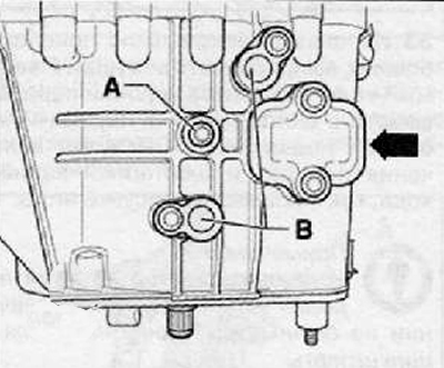
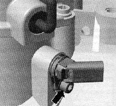
16. Screw in the reverse gear light switch (WITH), as shown in the figure below.
17. Install axle pins (IN) from the top of the gearbox housing, as shown in the figure below
18. Set the gear shift forks to the neutral position.
19. Apply an even layer of sealant (AMV 188 200 03) on the sealing surface of the gearbox cover.
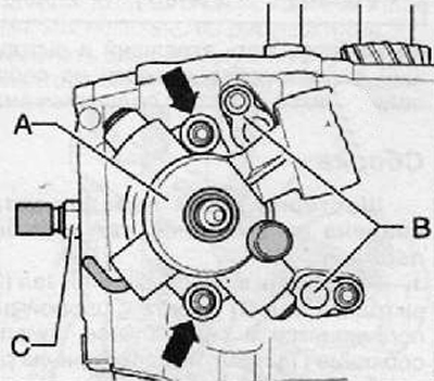
20. Install the gear selection and engagement shaft (A). Tighten the mounting bolts one by one (arrows), as shown in the figure below.
Vehicles with start-stop system
21. Insert and fix the neutral gear mechanism of the gearbox with the fastening bolt (arrow), as shown in the figure below.
For all vehicles
22. Install and tighten the mounting bolts (A) gearbox shaft bearings as shown in the figure below.
Note. Gradually tighten the mounting bolts in several steps (A) with the required tightening torque, crosswise, starting with the central bolts.
23. Borrow a nut (IN) mechanism for selecting and engaging gears, as shown in the figure below.
24. Install the input and output shafts of the gearbox together with the bearing support on the special tool (Т10083), as shown in the picture below
Installing the fifth gear manually
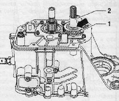
25. Top sleeve (arrow) directed towards the gearbox cover. Install 5th gear (1) and sleeve (2), if the gear is installed without pressing.
26. Install fifth gear (1) and sleeve assembly (2), as shown in the figure below.
Pressing the fifth gear
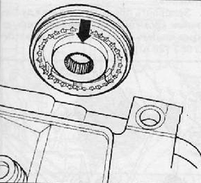
27. Using a set of special tools and a hydraulic press, press the fifth gear onto the gearbox shaft (1), as shown in the figure below.
28. Install the sleeve on the fifth gear (2).
Continued for all versions
29. Install the fifth gear sliding clutch with the fifth gear synchronizer ring and needle bearing.
The figure below shows the installation position for the 5th/6th gear synchro. Outer sleeve (arrow) is directed towards the fifth gear and towards the gearbox housing.
Press in 5th/6th gear synchroniser sliding sleeve if 5th gear (1) mounted on the shaft together with the bearing and the synchronizer ring.
Attention. Put on gloves before starting the operation.
30. Heat the inner ring of the needle bearing of the sixth gear to a maximum of 100 degrees Celsius, then press it onto the gearbox shaft.
31. Install the sixth gear synchronizer ring.
32. Install the 6th gear together with the needle bearing as shown in the figure below.
Attention. Use protective gloves for the operation.
33. Heat up to 100 degrees Celsius the inner ring of a cylindrical roller bearing (A), and then press it onto the gearbox input shaft as shown in the figure below.
34. The figure below shows the installation position of the sixth gear. The protrusion of the larger sleeve is directed towards the fifth gear
35. Move sliding sleeve (A) the synchronizer of inclusion of the fifth-sixth transfer in neutral position. This allows the freely rotating 6th gear to rotate freely while the gear is being pressed onto the output shaft.
Attention. Special protective gloves must be used for this operation.
36. Heat the sixth gear to a maximum of 100 degrees Celsius.
37. Press the sixth gear onto the gearbox shaft, making sure that the teeth rotate freely (IN) and planted tightly (WITH) gears are engaged as shown in the figure below.
38. Heat the inner race of a cylindrical roller bearing (A) up to a maximum of 100 degrees Celsius, then press it onto the output shaft of the gearbox as shown in the figure below.
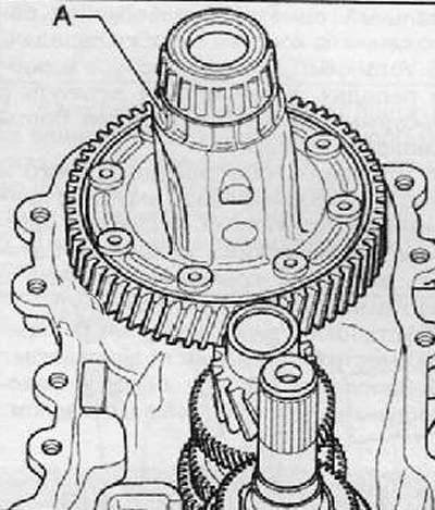
39. Install the differential assembly with the final drive driven wheel in the gearbox housing (A), as shown in the figure below.
40. Apply special sealant (AMV 188 200 03) uniform layer on mating surfaces.
41. Install the clutch housing to the gearbox housing assembly.
42. Turn the gearbox assembly on the stand and install the clutch housing up.
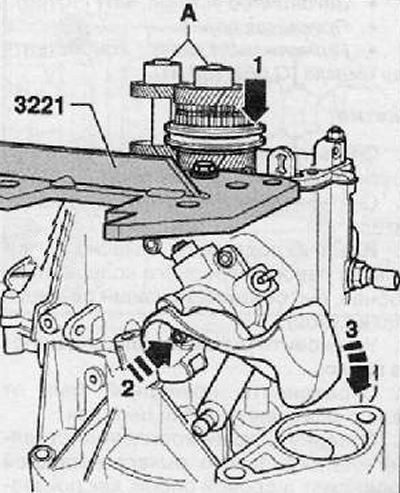
43. Before the final tightening of the fastening bolts (A), it is necessary to engage the fifth gear by moving the synchronizer to the stop (arrow 1) and first gear by turning the gear selection and engagement lever (arrow 2 and 3), as shown in the figure below. Thus, both shafts of the gearbox will be blocked.
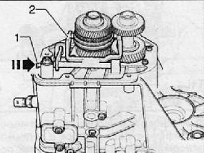
44. Insert the fifth-sixth gear forks (2) and press on the axle bolt (1) as far as it will go in the direction of the arrow, as shown in the figure below.
45. Apply an even layer of special sealant to the mating surface on the gearbox housing.
46. Install the gearbox housing cover. Install and tighten the cover bolts to the required torque.
47. Install both flanges of the right and left drive shafts together with the pressure springs, thrust plates and conical rings. Tighten the flange fasteners to the required tightening torque.
48. Install the shift fork together with the release bearing.
49. Fill the gearbox with the recommended gear oil.