
Removing
1. Disconnect the negative terminal from the battery, turn off the ignition.
2. Remove the battery assembly. Remove the battery support plate.
3. Remove the air filter housing assembly (see the relevant section in chapter Intake and exhaust system).
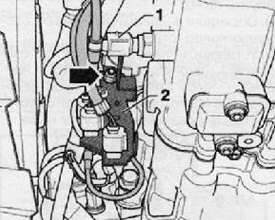
4. Remove the lock washer (1) gear shift cable (2) connected to the shift lever as shown in the figure below.
5. Pull and disconnect the gear shift cable lock.
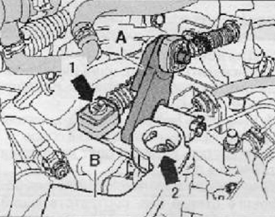
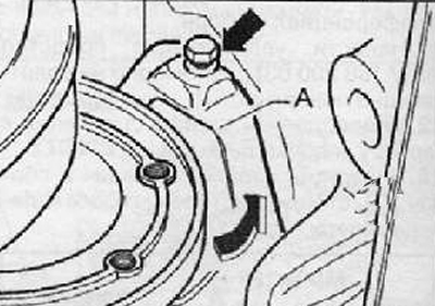
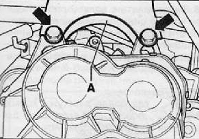
6. Remove gear selector (A) together with the shift cable lock as shown in the figure below.
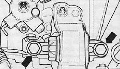
7. Loosen the fastening nut (arrow 2) and remove the shift lever (IN) from the gearshift main shaft as shown in the figure below.
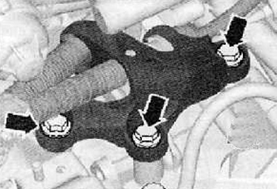
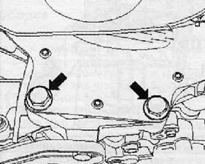
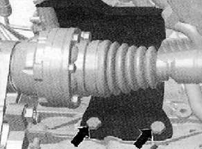
8. Unscrew the fastening bolts (arrows) and disconnect the Bowden cables from the gearbox as shown in the figure below.
9. Set aside and hang the selector and shift cables using a suitable piece of wire.
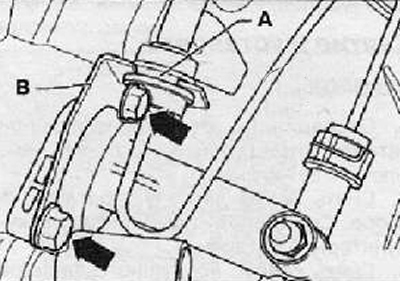
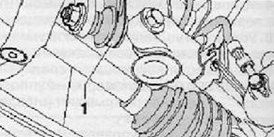
10. Disconnect the pipe together with the hose (A) from mounting bracket (IN) on the gearbox housing as shown in the figure below.
11. Remove the slave cylinder (IN) hydraulic clutch release. Take the clutch release cylinder to the side, hang it with a wire cutter. Do not disconnect the hydraulic drive pipes from the clutch release slave cylinder.
Attention. Do not press the clutch release pedal!
Vehicles with start-stop system
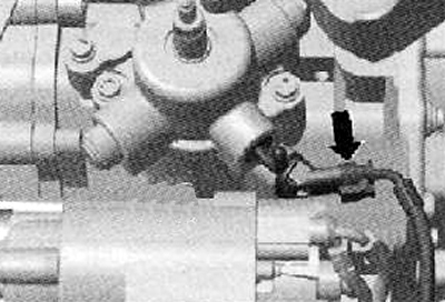
12. Disconnect the wiring harness connector (arrow) from the transmission neutral position actuator, as shown in the figure below.
For all vehicles
13. Unscrew the fastening screw and disconnect the wire from the gearbox housing «masses».
14. Unscrew the upper bolts securing the gearbox to the engine assembly.
15. Unscrew the top bolt of fastening of a starter in gathering.
16. Remove windshield wiper arms (see the relevant section in chapter Electrical equipment and electrical systems).
17. Remove the cover of the expansion tank of the engine cooling system.
18. Remove the decorative plastic covers from the glasses of the shock absorber struts in the engine compartment.
19. Install a special device for hanging the power unit assembly (Т30099) with support beam (Т30099/1) and clamps for the special fixture MP9-200 and T30099 - MP 200/100-, as shown in the figure below.
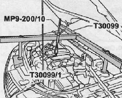
20. Using the spindle, tighten the power unit assembly. Do not lift the power unit under any circumstances.
21. Remove the soundproofing cover under the engine and gearbox assembly.
22. Disconnect the wiring harness connector (1) from the reverse light switch.
23. Remove mounting bracket (2) on the starter by unscrewing the fastening nut (arrow) and, if necessary, a cable harness holder, as shown in the figure below.
24. Remove the starter assembly (see the relevant section in chapter Engine electrical equipment).
25. Unscrew the mounting bolts and remove the protective plate, as shown in the figure below.
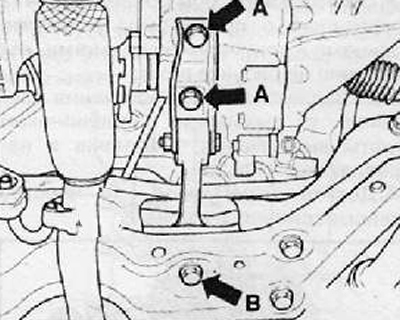
26. Unscrew the fastening bolts (arrow A) And (arrow B) and remove the oscillating support shown in the figure below.
27. Disconnect the exhaust pipe section from the subframe.
28. Unscrew the fastening nut and disconnect the rack from the anti-roll bar (1), as shown in the figure below. Carry out this operation on both sides of the anti-roll bar.
29. Turn the anti-roll bar and install with the lugs up.
30. Unscrew the mounting bolts and remove the protective shield of the drive shaft, as shown in the figure below.
31. Disconnect the drive shafts from the gearbox and hang them from the front suspension elements using pieces of wire.
32. Check if the protective plate is installed (A) above the right drive shaft flange as shown in the figure below.
33. Unscrew the mounting bolt and remove the protective plate by moving in the direction of the arrow, as shown in the figure below.
34. Unscrew the mounting bolts (arrows) transmission support assembly as shown in the figure below.
35. Using a special device for hanging the power unit, release the interference by rotating the spindles.
Note. When lowering the power unit, make sure that the gearbox does not touch the front suspension subframe assembly.
Note. You should have access to the mounting bolts (arrows) gearbox console.
36. Unscrew the mounting bolts (arrows) and disconnect the gearbox from the console (A), as shown in the figure below.
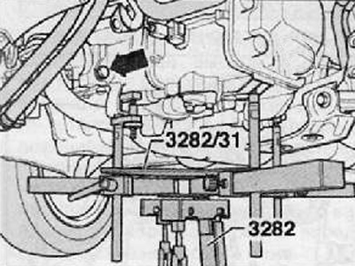
37. Insert gearbox support (3282) in the support of the power unit (VAG 1383 A).
38. Install the adjusting plate (3282/31) on a support (3282) (adjust the installation of the plate in only one position).
39. Align the gear levers with the holes in the adjusting plate.
40. Screw in fasteners (A), as shown in the figure below.
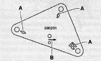
41. Place a special hydraulic jack under the engine. Adjust the position of the jack so that the arrow B on the adjusting plate points in the direction of the vehicle.
42. Adjust the plate so that it is parallel to the gearbox, then fix it.
43. Unscrew the bolt securing the gearbox to the engine (arrow), shown in the figure below.
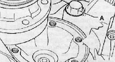
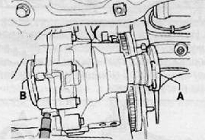
44. Unscrew the bolt securing the gearbox to the engine from the side of the right flange of the drive shaft (A), as shown in the figure below.
45. Remove the gearbox from the guide pins and carefully slide it through the front suspension subframe.
46. Ask an assistant to shift the engine towards the radiator. When performing this operation, make sure not to damage the radiator of the cooling system.
47. Lower the gearbox with the differential housing down.
48. After performing all the operations described above, lower the gearbox assembly.
49. Holding the gearbox by the flanges of the drive shafts (A) And (IN) pass it through the stretcher.
50. Press and move the left wheel arch liner down and slightly to the left so that the gearbox does not touch the liner.
51. Gently lower the gearbox through the front suspension subframe.
52. Change the location of the gearbox on the support (3282), after lowering.
Note. After lowering the gearbox, check all wires and pipes with hoses.
Installation
1. Installation is made in reverse order to removal.
Note.
- Clean the splines of the input shaft of the gearbox and apply a special lubricant to its surface.
- Check and make sure. that the clutch disc moves freely along the input shaft of the gearbox.
- After installing the gearbox, make sure the clutch disc is properly installed.
- Check and make sure. that guide pins are installed in the cylinder block.
- Install starter assembly (see the relevant section in chapter Engine electrical equipment).
- Connect the drive shafts to the gearbox.
- Connect the selector and shift cables to the gearbox.
- Install the battery and battery support.
- Install the air filter housing (see the relevant section in chapter Intake and exhaust system).
- Install the soundproofing cover of the engine compartment.
- Connect wire to battery «masses». Reset error after connection.