2. Substitute a special trapping bath for combustible materials.
3. Drain the gear oil into a prepared bath.
4. Remove the clutch release fork together with the release bearing and guide sleeve.
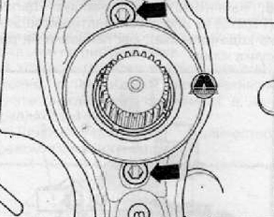
Loosen the fixing screws (arrows), shown in the figure below.
Remove the release fork with clutch release bearing and guide sleeve from the drive shaft and ball stud as shown in the figure below.
5. Remove the right drive shaft with flange.
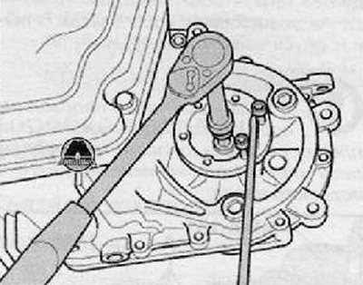
For this purpose, screw two bolts into the flange, holding the flanged shaft with the mounting lever, as shown in the figure below.
Remove flanged shaft with compression spring, thrust washer and taper washer.
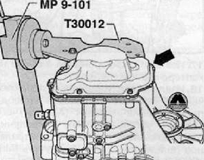
6. Unscrew the mounting bolts and remove the cover (arrow) gearbox housing shown in the figure below.
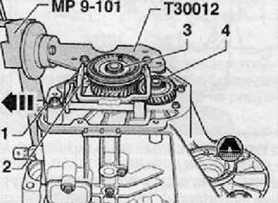
7. Remove the pin (1) shift forks for engaging 5th gear (2), remove the shift fork as shown in the figure below.
8. Remove retaining ring (3) 5th gear synchronizer as shown in the figure below.
9. Remove retaining ring (4) 5th gear shown in the figure below.
10. Remove the 5th gear synchronizer gears and carriage as shown in the figure below.
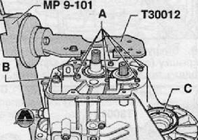
11. Unscrew the locking screws (A) from the bearing bracket of the output and drive shafts, as shown in the figure below.
12. Unscrew the fastening nut (IN) reverse gear fork shown in the figure below.
13. Remove the left shaft with flange (WITH), as shown in the figure below.
14. Rotate the gearbox in the assembly stand so that the clutch housing is at the top.
15. Unscrew the connecting screws of the clutch housing and gearbox housing.
16. Carefully release the clutch housing by alternating lever movements around the perimeter of the flange without damaging the sealing surfaces of the clutch housing and gearbox housing.
Note. During extraction, it is necessary to ensure that the clutch housing is not warped and the roller bearings of the drive and driven shafts are not damaged.
17. Remove the differential assembly from the gearbox housing.
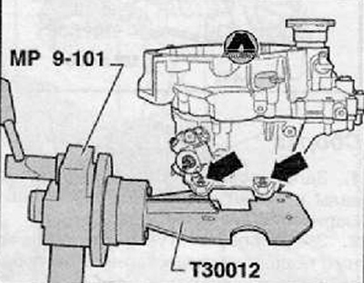
18. Remove the shift control shaft with gear shift cover (A), for which the shift control shaft must be set to the neutral position. Then unscrew the fixing screws (arrows) and remove the shift control shaft from the gearbox housing as shown in the figure below.
19. Remove the bearing journals shown in the figure below (IN) on the top of the gearbox.
20. Unscrew the reverse light switch -F4- (WITH), shown in the figure below.
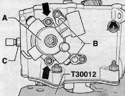
21. Remove the screw (A) reverse gear axle bearings.
22. Remove bearing journals (IN) on the underside of the gearbox as shown in the figure below.
Note. When removing the gearbox, do not remove the cover shown in the figure below (arrow).

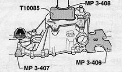
23. Press out the input and output shafts together with the bearing bracket, shift forks and reverse gear as shown in the figure below.
Note.
- Place the gearbox housing on the pressure plates (MPZ-406 (VW 401) And (MPZ-407 (VW 402) so as not to damage the centering sleeves.
- When pressing in, the parts must be secured, if necessary with the involvement of a second mechanic, so that they do not fall.
- The bearing bracket for deep groove ball bearings must always be replaced after removal.
24. Press the drive and driven shafts out of the deep groove ball bearing bracket as shown in the figure below.