Note.
- Necessary special devices, control and measuring devices, as well as auxiliary means:
- Universal fixture (MPZ-419 (VW 771).
- Puller (MP3-419/37 (VW 771/37).
- Mounting tool (MPZ-434 (3066)).
- driving sleeve (Т10148)
- Receiving bath for collecting fuels and lubricants.
- Sealing grease (G 052 128 A1).
Removing
1. Remove the lower engine guard.
2. To establish a steering wheel to the right against the stop.
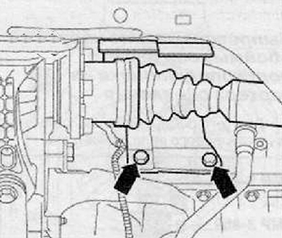
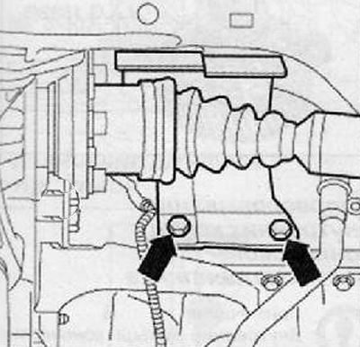
3. Remove the drive shaft heat shield from the motor, if fitted (arrows), as shown in the figure below.
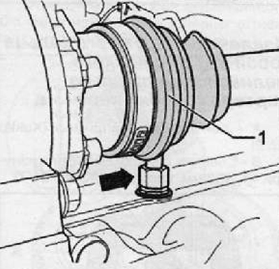
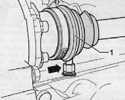
Disconnect drive shaft (1) from the flanged shaft as shown in the figure below (for details, see the relevant section in chapter Drive shafts).
5. Suspend the drive shaft as high as possible. Do not damage the protective paintwork on the drive shaft.
6. A special receiving bath should be placed under the engine and gearbox to collect fuels and lubricants.
7. If necessary, unscrew the turbocharger lubrication drain line from the engine (arrow), as shown in the picture below
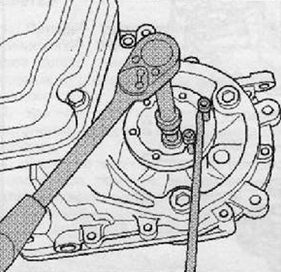
8. Unscrew the bolt securing the flange shaft, for this purpose, screw two screws into the flange and hold the flange shaft with the assembly lever, as shown in the figure below.
9. Remove the flange shaft including the spring from the gearbox housing.
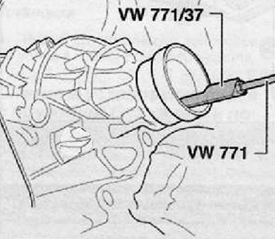
10. To take an epiploon together with the plug. There is a shoulder in the inner diameter of the bushing.
Puller (VW 771/37 (MPZ-419/37)) should be installed just behind the shoulder in the bushing as shown in the figure below.
During extraction, firmly press the puller (VW 771/37 (MP3-419/37)) to the bushing.
Installation
1. Clear space for the O-ring in the gearbox.
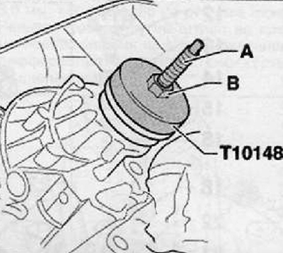
2. Pressing in the stuffing box with the bushing.
- A - Screw on the threaded rod from the installation tool kit (MP3-434 (3066)) into the threaded part of the differential.
- B - Nut M12 with washer.
3. Turning the nut (IN) it is necessary to press the stuffing box with the bushing through the pressure piece (Т10148) all the way. as shown in the picture below.
4. Fill the space between the working edges up to half with sealing grease (G 052 128A1).
5. Install the flanged shaft into the gearbox housing.
6. The flanged shaft should be attached with a cone head screw and tightened to the correct torque.
7. If the turbocharger lubrication drain line was disconnected from the engine, then it should be reinstalled (arrow). Tighten the union nut to the required torque.
8. Connect the drive shaft (1) to the flange.
9. Install heat shield for drive shaft (arrows), if it is available. Install and tighten the protection bolts to the required tightening torque.
10. Check the gear oil level in the gearbox (see relevant section in this chapter).
11. Install the lower engine guard.