
Removing
Note.
- Necessary special devices, control and measuring devices, as well as auxiliary means:
- Gear box attachment (3282).
- Mounting plate (3282/31).
- Device for removing and installing the engine and gearbox (e.g. -VA G 1383/A-).
- transport device (MPZ-478 (3336)).
- Fixing suspension device (MP9-200 (10-222A)).
- Tip (MP9-200/3 (10-222A/3)).
- Hook for MP9-200 and T30099 (MP9-200/10 (10-222A/10)).
- Grease (G 000 100).
1. Remove the top decorative engine cover.
Note.
- All cable connections that were loosened or disconnected during removal must be reattached in the same place when reinstalled.
- After disconnecting and then connecting the wire connecting the battery terminal to ground (corps) vehicle, some additional work needs to be done.
2. Disconnect, with the ignition off, the wire connecting the battery terminal to ground (corps) car.
3. Remove the air filter (for details, see the relevant section in chapter Intake and exhaust system).
4. Remove the battery and battery holder (for details, see the relevant section in chapter Engine electrical equipment).
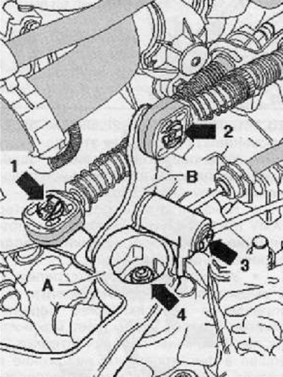
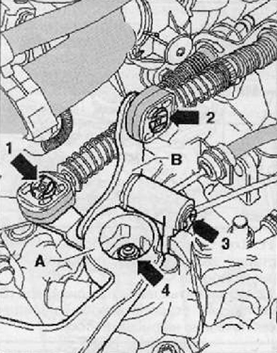
5. Remove retaining ring (arrow 1) cable-operated gear shift with shift lever (A), as shown in the figure below.
6. Remove the shift cable drive from the trunnion.
Metal selector lever
7. Remove retaining ring (arrow 2) cable drive for selective gearshift control with selector lever guide (IN), as shown in the figure below.
8. Remove the cable drive for the preselective gearshift control from the trunnion.
9. Removing the retaining ring (arrow 3) from the selector lever (IN), remove the selector lever as shown in the figure below.
Note. Retaining rings must always be replaced.
Plastic selector lever
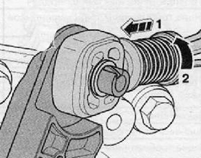
Note. To prevent damage to the cable drive for the selective shift control device, it is necessary to separate the locking device of the flexible shaft (Bowden cable) from the cable drive to the selective shift control device before proceeding with the extraction.
10. Having tightened the locking device to the stop forward in the direction (arrows 1), fix it then by turning it to the left in the direction (arrows 2), as shown in the figure below.
11. The preselector guide lever must be removed together with the flexible shaft locking device (Bowden cable).
Continuation for all cars
12. Remove the gear lever (A), for which you need to unscrew the nut (arrow 4), as shown in the figure below.
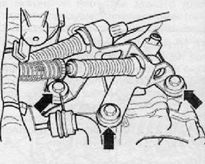
13. Remove the counter support of the flexible rollers (Bowden cables) (arrows), as shown in the figure below.
14. Then tie the shift cable and the cable for the preselective shift control at the top.
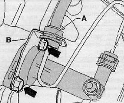
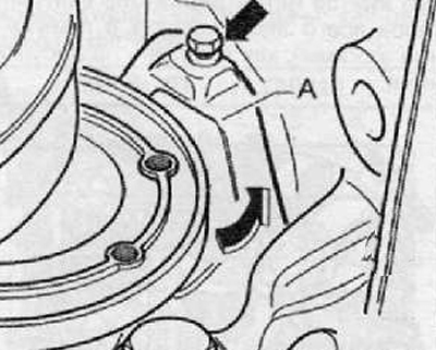
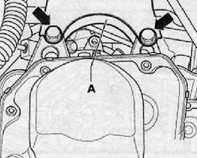
15. Remove the pipe and hose line (A) from the holder (IN) on the gearbox (if the holder is installed), as shown in the figure below.
16. Remove the clutch release slave cylinder (arrows), set it aside and secure with wire. Do not disconnect wire.
Note. Do not depress the clutch pedal.
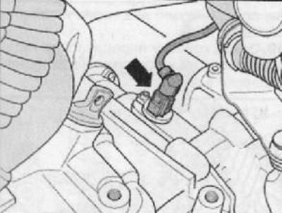
Cars with petrol engines
17. Disconnect the wiring harness connector (arrow) from speedometer sender -G22- (if installed), as shown in the figure below.
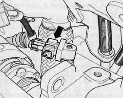
Vehicles with diesel engines
18. Disconnect the wiring harness connector (arrow) from speedometer sender -G22- (if installed), as shown in the figure below.
Continuation for all cars
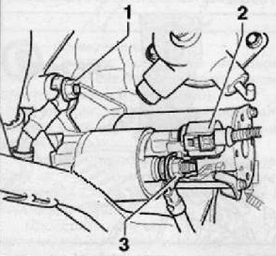
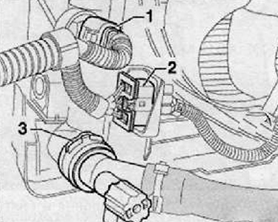
19. Remove the wire for a short to ground (frame) from the bolt connecting the engine and gearbox (1) (some types of motor wire is not connected), as shown in the figure below.
20. Disconnect the wiring harness connector (2), shown in the figure below.
21. Remove starter wire for short to "mass" (frame) (3), as shown in the figure below.
22. Put all electrical wires aside.
23. Unscrew the upper bolts connecting the engine and gearbox.
24. Remove the top starter mounting screw.
25. Hang out the power unit assembly.
For this:
Remove the windshield wiper arms.
Remove the cap of the expansion tank of the engine cooling system (for details, see the relevant section in the chapter Cooling system).
Remove the plastic covers from the upper shock absorber mounts in the engine compartment.
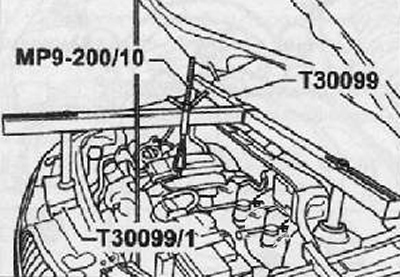
Install a special device for hanging the power unit (Т30099) along with the beam (Т30099/1) and capture for the MP9-200 and T30099 MP-200/10 device.
Note. Fix a special device for hanging the power unit.
26. Using a lead screw (spindle) slightly prestress the engine-gearbox assembly.
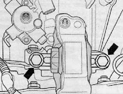
27. Remove fixing screws (arrows) from the gearbox bearing, as shown in the figure below.
28. After removing the left front wheel, raise the car.
29. To remove the lower protective casing of the engine.
30. Remove wheel arch liner (wings) left front wheel (see the relevant section in chapter Body).
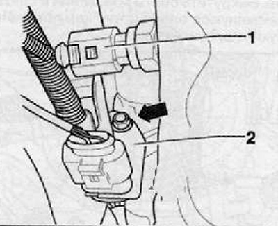
31. Disconnect the wiring harness connector (1) from the reverse gear switch as shown in the figure below.
32. Unscrew the mounting bolts and remove (arrow) with gearbox mounting bracket (2), set it aside with the wires as shown in the figure below.
33. Remove starter assembly (for details, see the relevant section in chapter Engine electrical equipment).
34. Remove the front of the exhaust pipe (for details, see the relevant section in chapter Intake and exhaust system).
35. Unscrew the mounting bolts and remove the heat shield (arrows) (if it is installed) for the inner CV joint of the right drive shaft, as shown in the figure below.
36. Remove drive shafts with flanges; turn the steering wheel all the way to the left.
37. Unscrew the fastening bolt and remove (if installed) small protective sheet (A) for flywheel behind right flanged shaft (arrow), as shown in the figure below.
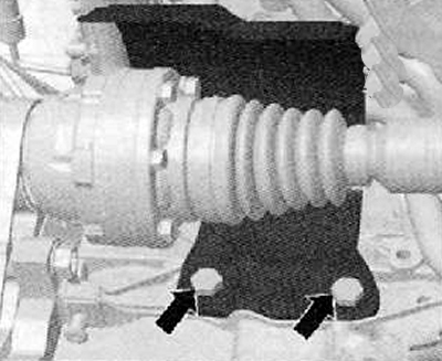
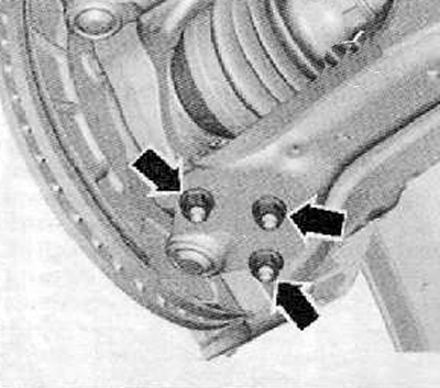
38. Unscrew the fastening nuts (arrows) lower front suspension arm to the ball joint as shown in the figure below.
39. Unscrew the mounting bolts and remove the oscillating support (arrows), shown in the figure below.
40. Disconnect the wiring harness connector (2), shown in the figure below.
Note. Unscrew the air conditioning pipe holder (if equipped) from the fan bracket.
41. Unscrew the fastening screws (arrows), remove the fan holder downwards (the new models no longer have screws, and the fan holder is just pushed into the clamps), as shown in the figure below.
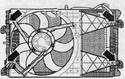
42. After releasing the fan shroud on the latch, using a suitable tool, remove it, as shown in the figure below.
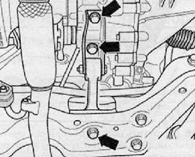
43. Unscrew the mounting bolts shown in the figure below by arrows. Then remove the mounting bracket (A) from the gearbox as shown in the figure below. Loosen the fixing screws (arrows) gearbox bracket as follows.
Lower the engine-gearbox unit through the lead screw to such an extent that access to the bolts of the gearbox bracket (A) from the wheel arch of the left wheel.
Note. When lowering the engine-gearbox assembly, make sure that the gearbox does not touch the front suspension subframe.
44. Unscrew the bolt connecting the engine and gearbox above the right flange shaft.
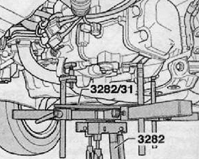
45. Install the gearbox mount (3282) into a device for removing and installing the engine and gearbox, for example (VAG 1383/A).
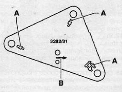
46. Assemble, using the technology below, a device for removing and installing the engine and gearbox with a device for attaching the gearbox (3282), mounting plate (3282/31) for gearbox "02T" and fasteners:
Put the mounting plate (3282/31) on the gear box mount (3282) (Mounting plate can only be installed in one single position).
Adjust the position of the arms of the gearbox mount to the holes in the mounting plate.
Screw in fasteners (A) according to the marks on the mounting plate, as shown in the figure below.
47. Place the tool for removing and installing the engine and gearbox under the car, while the arrow symbol (IN) on the mounting plate points in the direction of travel of the vehicle, as shown in the figure below.
48. Aligning the mounting plate parallel to the gearbox, fix its locking clips.
49. Remove the lower mounting bolts connecting the engine and gearbox.
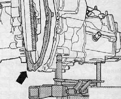
50. Having pressed the gearbox from the engine, take it to the subframe of the front suspension assembly.
For vehicles with 1.4/51 kW engine
51. While lowering the gearbox, remove the inserted spacer (arrow), shown in the figure below.
Continuation for all cars
52. Push the engine towards the radiator. This operation must be carried out by a second mechanic.
53. Carefully lower the gearbox assembly.
54. During lowering, the position of the gearbox should be changed using the lead screws of the gearbox mounting device (3282).
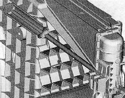
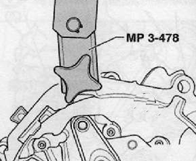
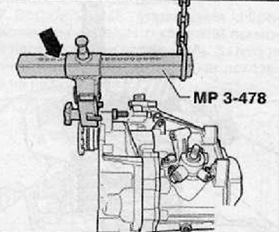
55. Connect the transport device to the clutch housing (MPZ-478 (3336)), as shown in the figure below.
56. Adjust the console on the movable part using the lock. Number of visible holes (arrow) = 5.
57. Raise the gearbox with a workshop crane and transport device (MPZ-478 (3336)).
58. Put the gearbox aside on the transport pallet.
Installation
Note. Before proceeding with installation, unscrew the screw plug to check the oil level and, if necessary, add gear oil.
1. Installation is made in reverse order to removal. Follow the installation of the unit in the car without pretensioning.
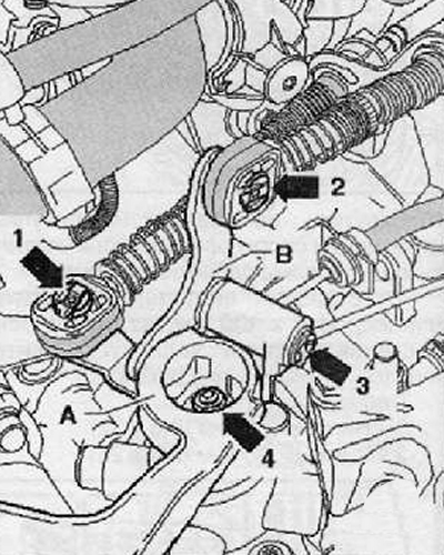
2. Retaining rings shown in the figure below (1), (2) And (3) should be replaced after each extraction.
3. After installation, check the oil level in the gearbox.
Note.
- After cleaning the splines on the drive shaft, lubricate them lightly with grease (G 000 100).
- The clutch disc on the input shaft must be free to move back and forth.
- When replacing the gearbox, make sure that the spacer plate between the engine and gearbox is correctly installed.
- Check for the presence of centering bushings in the cylinder block for centering the gearbox; insert them if necessary.
- Assemble the exhaust system so that it is stress-free.
- Installation of starter and wires.
- If necessary, adjust the gearshift drive.
- Add coolant.
- After disconnecting and then connecting the wire connecting the battery terminal to ground (corps) vehicle, some additional work needs to be done.
- Check vehicle geometry.