



Removal and installation
Note: The engine is removed from underneath the engine compartment downwards together with the transmission. All removed electrical wiring ties and clamps must be in their original places during installation. The electrical wiring and hoses should be routed in the same way as they were before removal. Therefore, you should remember or sketch/photograph the location of clamps, electrical wiring and hoses.
1. Remove the top engine cover. To do this, pull it out of the supporting hinge sockets one by one (1-4 in illustration 34.1a), grasping the edges of the lid as deeply as possible. To install, press the cover into the sockets until you feel it lock into place. It may be necessary to adjust the hinge sockets to the correct position before installation (see illustration 34.1b).
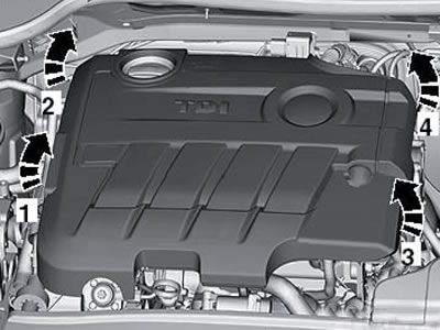
34.1a. Removing the top engine cover
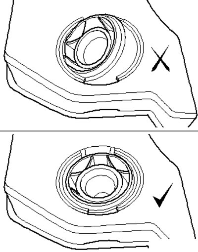
34.1b. Correct (bottom) and incorrect (top) positions of the socket for the upper engine cover
2. Remove the air cleaner together with the MAF sensor and intake tube (see Chapter 4).
3. Remove the battery and its holder (see Chapter 5).
4. On CFHC and CFJA engines, disconnect the following connectors on the engine compartment bulkhead (see illustration): sensor "G648" EGR No. 4 (2, orange), sensor "G235" EGR No. 1 or temperature sensor after turbocharger "G507" (3, black), lambda probe "G39" (4, black) and EGR sensor No. 3 "G495" (6, brown).
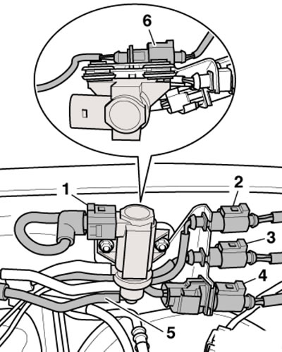
34.4. Sensors and vacuum hose on the engine compartment bulkhead
5. Disconnect the vacuum hose (5 in illustration 34.4) from the electromagnetic valve "N75" for regulating the boost pressure.
6. Drain the coolant (see Chapter 3).
7. Disconnect the connector (1 in illustration 15.11) sensor "G266" of engine oil level and temperature. Remove the bracket (2) for the G266 sensor wiring harness from the powertrain support.
8. On FWD models, if equipped, remove the right drive shaft heat shield (see illustration).
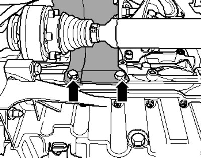
34.8. Fastening the heat shield of the right drive shaft
9. Remove the wheel arch liners from both front wheel arches (see Chapter 11).
10. Disconnect the left drive shaft from the transmission flange (see Chapter 8).
11. Remove the exhaust pipe with the particulate filter (see Chapter 4).
12. On AWD models, separate the driveshaft from the transmission (see Chapter 8).
13. Loosen the nut of the left stabilizer bar (2 in illustration 5.6) and press it away from the stabilizer. Then remove the three nuts (3) of the ball joint and separate it from the suspension arm. Turn the steering wheel all the way to the left, pull the ball joint outward and, using a suitable strap (A), secure the left drive shaft to the suspension strut so that the CV joint does not bend too much. Insert a pin into the control arm to stabilize the ball joint.
14. Remove the bolts (arrows in the illustration), release the coolant hose (1), loosen the clamp (3), disconnect the connector (2) of the "G31" sensor and remove the right air pressure pipe.
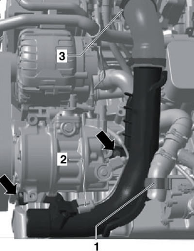
34.14. Removing the right air pressure tube
15. Unscrew the bolt (arrow on the illustration) and move the coolant circulation pump No. 2 "V178" to the side.
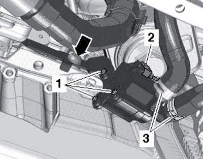
34.15. Fastening of the pump "V178"
16. Remove the vacuum hose (2) from the turbocharger vacuum element and disconnect the vacuum hose (3).
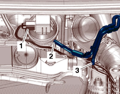
34.16. Vacuum hoses
17. Remove the vacuum hose from the brake booster (see illustration).
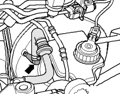
34.17. Vacuum hose on the brake booster
18. Disconnect the feeder (2 in the illustration) and return (1) fuel lines.
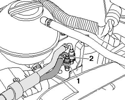
34.18. Fuel lines
19. Disconnect the connector (4 in the illustration) fuel temperature sensor "G81", loosen the clamps (2 and 3) and remove the supply and return fuel lines.
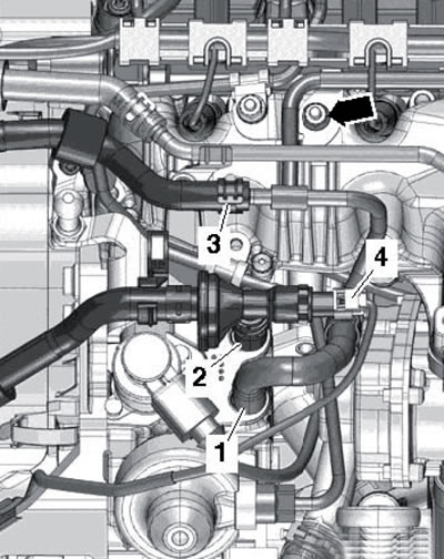
34.19. Sensor connector "G81" and fuel lines
20. Unscrew the bolt (1 in the illustration) and move the neck (2) of the washer fluid reservoir together with the tube to the side.
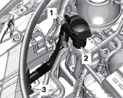
34.20. Removing the washer fluid reservoir neck
21. Release the fuel hose (2 in the illustration) from the bracket. Remove the fuel line bracket upward in the direction of the arrow and place it to the side. Disconnect the connector (1) of the additional fuel pump "V393" and unscrew the bolts (3).
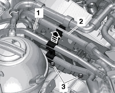
34.21. Fuel line bracket and auxiliary fuel pump connector
22. Loosen the bolt (1 in the illustration) 2 turns, unscrew the bolt (2) and loosen the nut (3). Separate the coolant line bracket from the fuel filter. Remove the fuel filter together with the connected hoses and remove the bracket together with the "V393" pump.
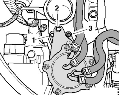
34.22. Removing the fuel filter and additional fuel pump
23. On models with refrigeration, remove the accessory drive belt (see Section 35) and remove the air conditioning compressor without disconnecting the refrigerant lines from it (see Chapter 3). Secure the compressor to the hood latch bracket with wire so that the refrigerant lines are not stretched or kinked.
24. Remove the fuse and disconnect the front ECM connector (see Chapter 5).
25. Remove the wiring harness guide plate retainer (see illustration 5.15) and pull it up from the bulkhead near the expansion tank.
26. Open all the wiring harness guides and set it aside (see illustration).
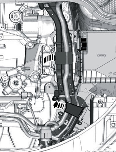
34.26. Wiring harness guides
27. Disconnect the connector (1 in the illustration 23.12) and open the bracket (2) under the electrical wiring guide. Release the engine wiring harness going to the ECM and lay it on the engine.
28. Disconnect the connector on the lower left side member (see illustration).
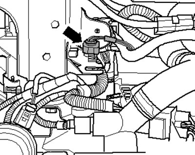
34.28. Connector on the left side member
29. Remove the clamp (arrow in illustration 23.15) protective cap (if available), disconnect the ground wire (1), disconnect the connector (2), pull back the protective cap and disconnect the B+ wire from the starter solenoid valve bracket.
30. Disconnect all remaining engine and transmission wiring connectors or disconnect the wiring harnesses from them.
31. Disconnect the coolant hoses from the heater radiator (see illustration).
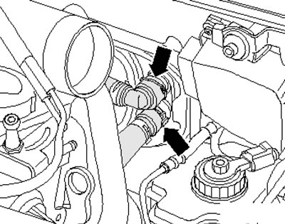
34.31. Coolant hoses on the heater radiator
32. On models with an additional heater, disconnect the coolant hoses from it, collecting the leaking liquid.
33. On models with a manual transmission, remove the gearshift mechanism from it and disconnect the pressure line from the breather/clutch slave cylinder (see Chapter 6).
34. On models with DSG, remove the gear shift mechanism from it.
35. Disconnect all remaining engine and transmission connections, coolant hoses, vacuum and vent hoses.
36. Secure the T10012 support to the cylinder block by tightening the nut (2 in the illustration) and bolt (1) with a force of 20 Nm. Insert the VAG1383A transmission jack into the T10012 support and support the engine to relieve its supports.
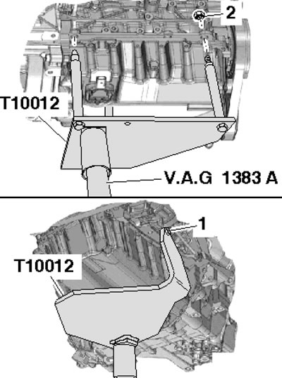
34.36. Support for lifting the power unit
37. Remove the bolts from the stepladder (see illustrations) fastening the right and left brackets (on the engine and transmission).
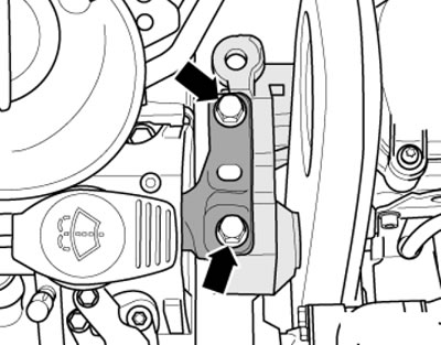
34.37a. Right engine support bolts
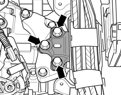
34.37b. Left engine mount bolts
38. Together with an assistant, carefully lower the power unit from the engine compartment using a jack. Rotate or move the power unit as necessary to prevent damage to its parts and engine compartment components.
39. Secure the engine to the mounting stand and separate the transmission from the engine (see chapter 6 or 7).
40. Installation is carried out in the same way as on the 1.4 l engine (see Section 15). A description of the inspection and adjustment of the power unit supports is given in the subsection below.
Checking and adjusting the powertrain supports
41. The details of the support fastenings are shown in the illustration.
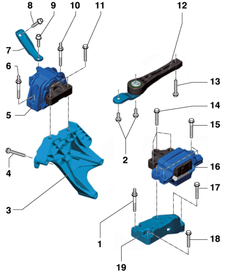
34.41. Powertrain support fastening parts 1. Bolt; 2. Bolt, strength class 10.9, must be replaced, 50 Nm then tighten to an angle of 90°; 3. Engine support bracket; 4. Bolt, subject to replacement, 40 Nm then tighten to an angle of 180°; 5. Engine support; 6, 10, 15. Bolt, subject to replacement, 40 Nm then tighten to an angle of 90°; 7. Connecting piece; 8, 9. Bolt, subject to replacement, 20 Nm then tighten to an angle of 90°; 11, 14. Bolt, subject to replacement, 60 Nm then tighten to an angle of 90°; 12. Swinging support; 13. Bolt, subject to replacement, 100 Nm then tighten to an angle of 90°; 16. Transmission support; 17. Bolt; 18. Bolt, only on models with "DQ250" transmission; 19. Transmission support bracket
42. When securing the engine mount to the cylinder block, tighten the bolts in the following sequence: (1-3 in the illustration) in three stages: first by hand, then with a force of 40 Nm, and finally, pull them to an angle of 180°.
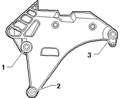
34.42. Engine Mount Bolt Tightening Sequence
43. To check the installation of the bracket, measure the distance (and in the illustration 15.42) between the bracket and the support, - it should be 10-13 mm. The cast edge of the support (2) should be parallel to the support lever (1), i.e. the distance (x) should be the same in front and behind. If the engine or transmission hits the side member when turning and the distance (a) is not 10-13 mm, adjust the bracket as described below.
44. Remove the battery and its holder (see Chapter 5).
45. Install support T30099 (see illustration) and evenly relieve the power unit supports by rotating both spindles.
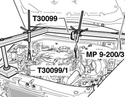
34.45. Unloading the power unit supports
46. Loosen the bolts securing the right and left brackets (see illustrations 34.37a-b) approximately 1 turn. If the bracket bolts were not yet replaced when installing the engine, screw in the new bolts one by one.
47. Move the power unit using a lever installed between the support lever (1 in illustration 15.42) and support (2) so that the distance (a) is 10 mm and the distance (x) is the same at the front and back.
48. Tighten the support bolts (see illustration 34.41).
49. Install the remaining parts.