
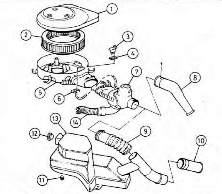
2.1 Air intake system with intake air temperature controller and air filter
1. Lid; 2. Filter element; 3. Pneumatic switch; 4. Gasket; 5. Housing; 6. Plate; 7. Air temperature control valve body; 8. Branch pipe; 9. Air intake hose; 10. Spigot (motor 136V); 11. Buffer (motor 136V); 12. Emphasis (motor 136V); 13. Resonator (motor 136V); 14. Warm air inlet.
Removing
1. Loosen the fastening brackets around the top cover of the air filter, unscrew the three bolts and lift the cover. Where available, release the vacuum hose from the mounts on the cover (see illustration).
2. Raise the air filter element.
3. Disconnect the throttle cable and disconnect the warm air pipe from the air temperature control valve body. On 136V engines, disconnect the air intake hose.
4. Slightly lift the shroud off the throttle body, then disconnect the vacuum tubes below the throttle body and the air inlet temperature control valve shroud. Label the tubes to avoid confusion during installation.
5. Disconnect the crankcase breather tube from the housing base.
6. The air filter housing can now be removed from the engine compartment.
7. On the 135V engine, you can remove the inlet pipe by unscrewing the screw.
8. To remove the intake air temperature control valve housing, disconnect the vacuum hose and loosen the two spring clips.
9. On 136V engines, a resonator is installed in front of the filter, which reduces noise when air is drawn in. The resonator is attached with two plastic nuts to the casing of the front suspension strut.
Installation
10. Install the air filter and air intake system components in the reverse order of removal. Check that the vacuum connections to the throttle body and the intake air temperature control valve housing are properly and securely connected. The air filter housing must be correctly installed on the throttle body so that there are no air leaks.