



Contents: Removal ⬇ Installation ⬇
Removal
Remove the door interior trim panel (see section Removal and installation interior door trim panels).
Interior door handle
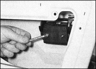
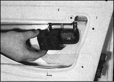
Remove the mounting screw, remove the washer and separate the inner door handle from the lock actuator rod. Remove the handle from the door.
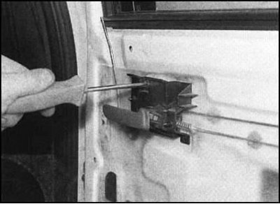 |
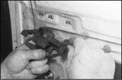 |
Front door lock cylinder
1. Remove the interior handle, then carefully peel the insulation film away from the door frame to expose the lock components.
2. Lower the window glass so that the bolts that attach it to the window regulator are accessible. Remove the bolts, remove the washers, then raise the glass completely and tape it to the door frame.
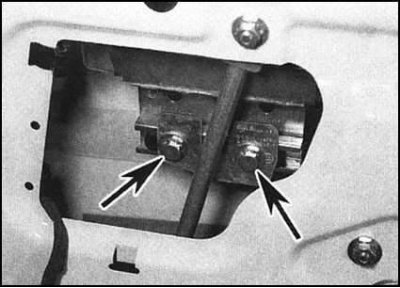
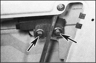
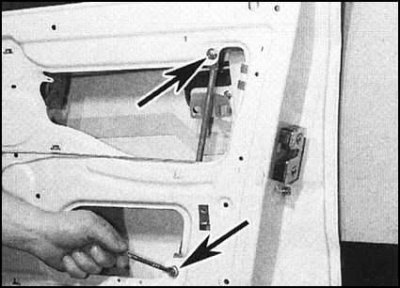
3. Loosen the nuts securing the rear window regulator pillar to the door.
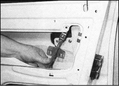
4. Move the stand away from the door lock.
5. Loosen the nut, release the fastening clamps and remove the anti-theft protection cover from the door, providing access to the lock assembly.
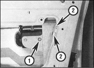
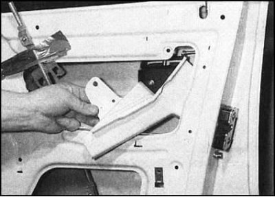
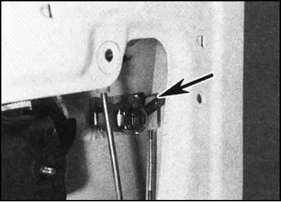
6. Separate the connecting rod from the spherical joint of the lock cylinder lever.
7. Slide the retaining clip to one side, then pull out the lock cylinder and remove the retaining clip.
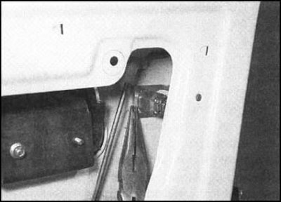 |
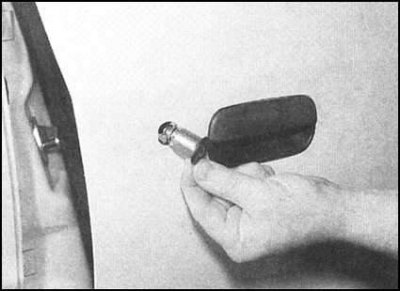 |
Front door lock
Note: The lock consists of two sections: external (including a latch) and internal (including actuator rods). The outer section can be removed without dismantling the finishing panel; below is a description of the procedure for removing the entire lock assembly.
1. Perform the procedures described in paragraphs 1 through 5 of the Front Door Lock Cylinder subsection.
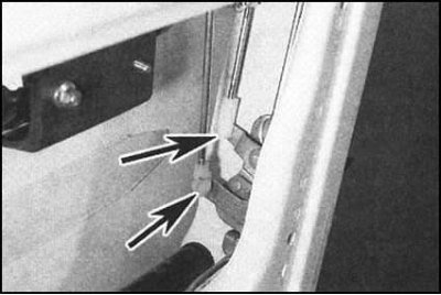
2. Disconnect the spherical joints of the actuator rods of the outer handle and the lock cylinder from the lock.
3. On models equipped with a single lock, follow the wiring from the door actuator to the connector and disconnect the latter. Also unscrew the additional bolt that secures the bracket of the inner section of the lock to the door, inside which the actuator is placed.
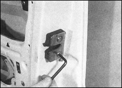
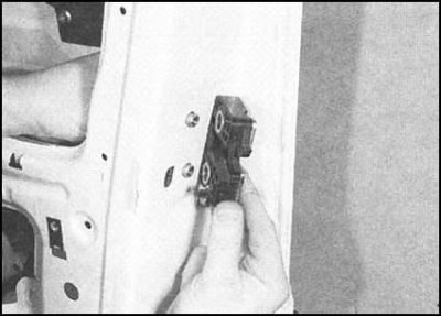
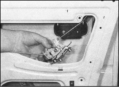
12. On all models, remove the two mounting bolts and remove the outer section of the lock assembly from the door. The inner section can now be removed from the door - try to remember the installation positions of the connecting rods of the inner button and the door handle.
Note: On models equipped with a single lock, the door actuator is removed together with the internal lock assembly.
 |
 |
Front door exterior handle
1. Perform the procedures described in paragraphs 1 through 5 of the Front Door Lock Cylinder subsection.
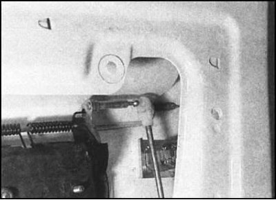
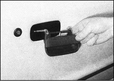
2. Disconnect the actuator rod from the outer handle spherical joint.
3. Loosen the mounting nut, remove the mounting bracket and remove the handle from the door.
 |
 |
Rear door outer handle
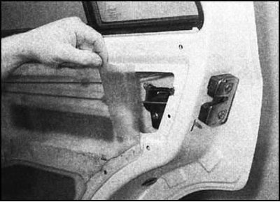
1. Carefully remove the insulating film from the door, providing access to the lock components.
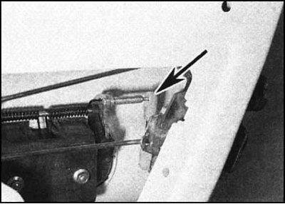
2. Disconnect the actuator rod from the outer handle spherical joint.
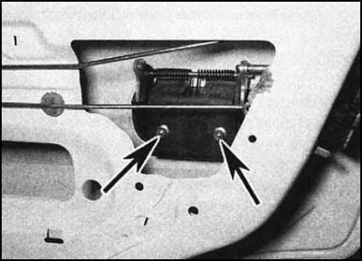
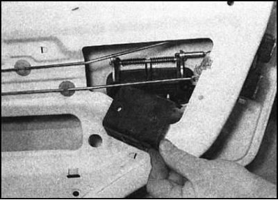
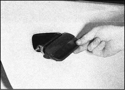
3. Loosen the mounting nuts, remove the mounting bracket and remove the handle from the door frame.
 |
 |
Assembling the rear door lock
Note: The lock consists of two sections: external (including a latch) and internal (including actuator rods). The outer section can be removed without dismantling the finishing panel; below is a description of the procedure for removing the entire lock assembly.
1. Remove the outside door handle.
2. Remove the mounting screws, washers and detach the inside door handle from its actuator rod. Remove the handle from the door.
3. On models equipped with a single lock, follow the wiring from the door actuator to the connector and disconnect the latter. Also unscrew the bolt securing the bracket of the inner section of the lock to the door.
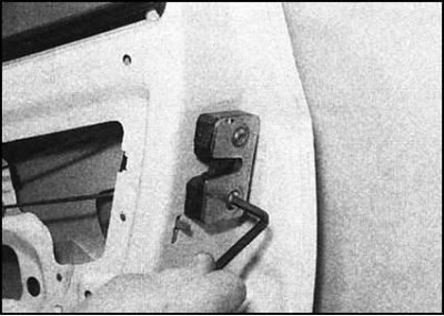
4. On all models, remove the two mounting bolts and remove the outer section of the lock assembly from the door.
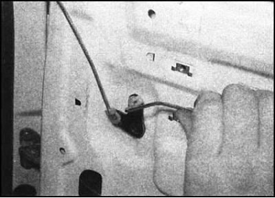
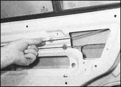
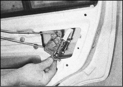
5. Disconnect the actuator rod from the inner button drive crank, then release both rods from the door and remove the inner section of the lock.
Note: On models equipped with a single lock, the door actuator is removed together with the internal lock assembly.
 |
 |
Installation
Installation is carried out in reverse order. Please note the following points:
- a) All fasteners must be tightened to the required torque;
- b) Check that the connecting rods are securely fastened to the spherical joints and that they are adjusted correctly. Adjustment is made by adjusting the position of the tip on the rod. Having achieved the desired result, firmly snap the rod onto the joint;
- c) Before replacing the insulation film and installing the door interior trim panel (see section Removal and installation interior door trim panels) check the proper functioning of the lock and both handles;
- d) Finally, check that the lock functions properly and that the door closes tightly. If necessary, loosen the fastening screws and adjust the position of the lock striker. Once the adjustment is complete, tighten the fasteners to the required torque.