



Contents: Removal ⬇ Installation ⬇
Front Door Assembly Components
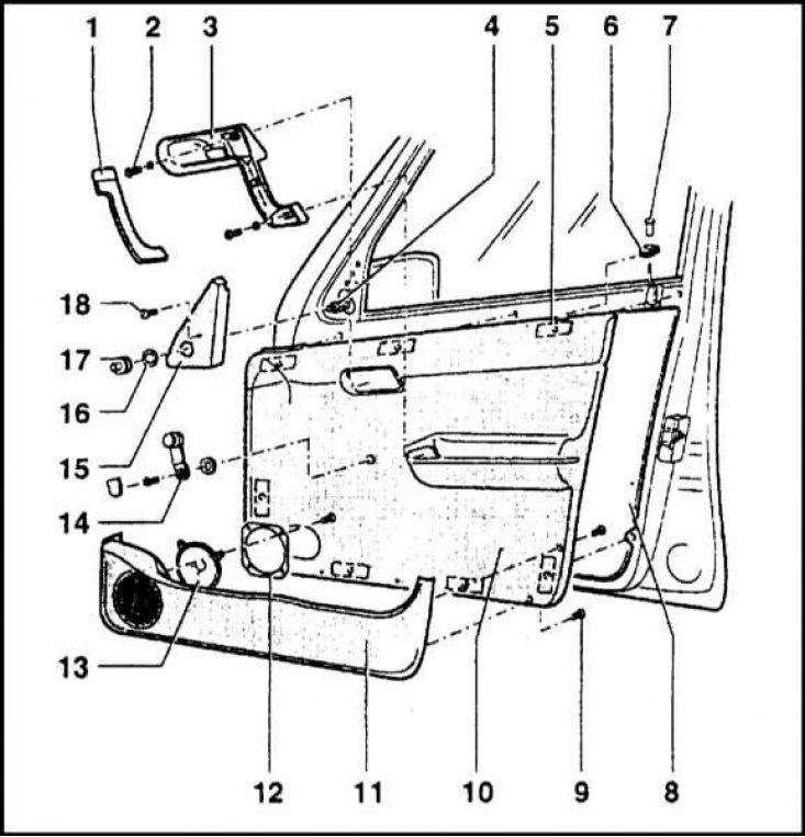
1 - Handlebar; 2 - Screw; 3 - Inner handle; 4 - Outside mirror drive rod; 5 - Locations of the fasteners; 6 - Overlay; 7 - Lock release button; 8 - Insulating film; 9 - Retainer; 10 - Interior trim panel; 11 - Pocket; 12 - Loudspeaker mounting flange; 13 - Loudspeaker; 14 - Window lifter handle; 15 - Decorative trim panel; 16 - Washer; 17 - Protective cover; 18 - Screw
Removal
Note: The method of fixing and the location of the fasteners for the interior trim panel on the door vary depending on the vehicle trim level and may differ from those shown in this Section.
Disconnect the negative cable from the battery.
Front door
1. The door assembly components are shown in the illustration.
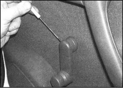
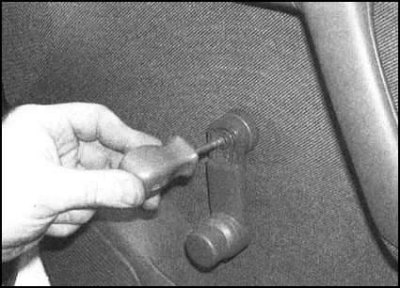
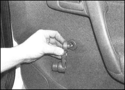
2. On models with manual window lifters, pry off the decorative cover of the window up/down handle. Unscrew the fastening screw and remove the handle from the spindle. Remove the spacer washer.
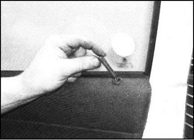
3. Unscrew the door lock release button, disconnecting it from the actuator rod.
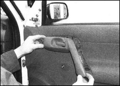
4. Lift the inside door handle, then carefully release the clips and remove the trim panel from the handle.
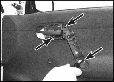
5. Remove the mounting screws and lift the door handle off the interior trim panel. If necessary, disconnect the rearview mirror switch wiring connector once it is accessible.
6. If equipped, remove the decorative cap and unscrew the screw securing the interior trim panel to the door.
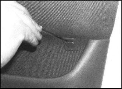
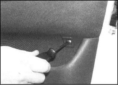
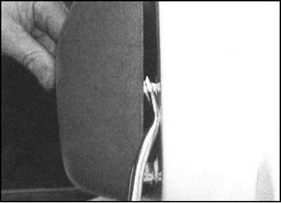
7. Carefully pry the panel, release it from the clips and separate it from the door frame. If the assembly is appropriate, release the electrical wiring from the panel and disconnect its connectors.
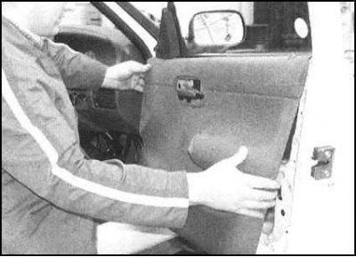 |
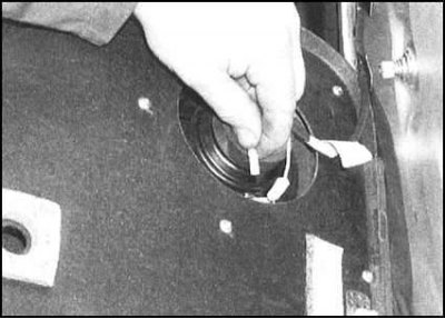 |
Back door
1. Follow the procedures described in paragraphs 2 through 5.
2. Carefully pry the panel up, release it from the clips and separate it from the door frame.
Installation
Installation is carried out in the reverse order. Before snapping the panel into the clamps, make sure that the wiring is correctly laid and threaded into the holes provided (with appropriate equipment).