



Contents: Manually adjustable mirror assemblies ⬇ Electric Mirror Assemblies ⬇ Mirror glass ⬇ Control switch ⬇
Outside rear view mirror assembly components
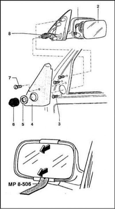
1 - Body; 2 - Mirror glass; 3 - Mounting screws; 4 - Decorative trim panel; 5 - Nut; 6 - Protective cover; 7 - Screw
Manually adjustable mirror assemblies
1. Typical components of an outside rearview mirror assembly are shown in the illustration.
2. Remove the rubber protective cover from the mirror adjustment handle, then loosen the nut on the regulator body.
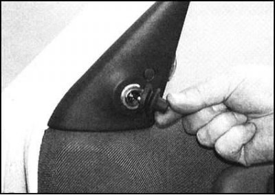
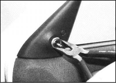
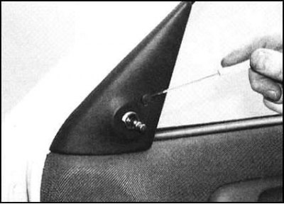
3. Pry off the decorative plug, loosen the mounting screw and remove the triangular decorative panel from the door.
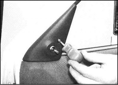
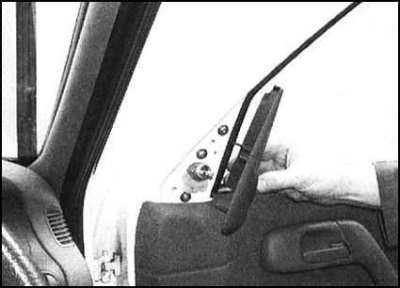
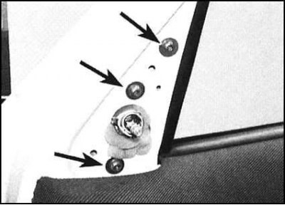
4. Remove the mounting screws and remove the mirror assembly from the door. Remove the insulating gasket installed between the mirror support and the door and check its condition. A defective gasket must be replaced.
5. Installation is carried out in reverse order.
Electric Mirror Assemblies
1. Pry up and remove the decorative plug, then unscrew the mounting screw and remove the triangular decorative panel from the door.
2. Remove the mounting screws and remove the mirror assembly from the door, disconnecting the electrical wiring connector at the same time. Remove the insulating gasket. A damaged gasket must be replaced.
3. Installation is carried out in reverse order.
Mirror glass
Note: The glass is snapped into the frame using clamps and can easily crack if the procedure is not performed carefully.
1. Tilt the mirror glass all the way up, then insert a plastic or wooden wedge between the base of the glass and the frame casing and gently pry the glass away from the drive motor/regulator.
2. Remove the glass from the frame and disconnect the electrical wiring from the heating element.
3. When installing, do not forget to connect the electrical wiring and ensure that the glass snaps securely onto the electric motor/regulator (apply force only to the central part of the glass in order to minimize accidental damage to the latter). After making sure that the glass is securely fixed, adjust the mirrors to the working position.
Control switch
See Chapter On-board electrical equipment.