



Contents: Removal ⬇ Installation ⬇
Removal
1. Loosen the nut securing the drive shaft to the rear wheel hub.
Attention:
- After loosening the hub nut, remove any load from the hub bearings.
- Otherwise, the weight of the vehicle will damage the wheel bearings and reduce their service life.
- While the vehicle is standing on its wheels, the drive shaft bolt can be turned no more than 90°.
- It is prohibited to move vehicles without installed drive shafts, as this will damage the wheel hub bearing. If the vehicle still needs to be moved, the following must be taken into account:
Install an outer CV joint instead of the drive shaft.
Tighten the CV joint mounting bolt to a torque of 120 Nm.
2. Remove the rear wheel assembly.
3. Using special mounting tape, secure the vehicle to the lift supports.
4. Disconnect the wiring harness connector from the rear wheel speed sensor of the ABS system.
5. Disconnect the wiring harness connector from the parking brake servo motor.
6. Remove the rear suspension spring (for more details, see the relevant section in this chapter).
7. Remove the rear wheel hub (for more details, see the relevant section in this chapter).
8. Remove the mudguard.
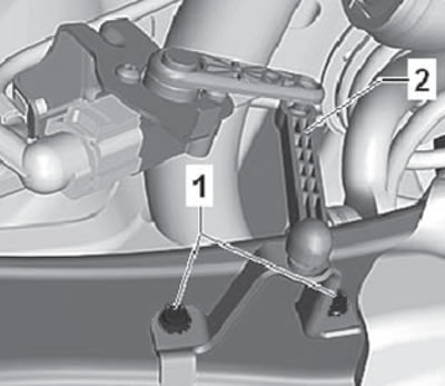
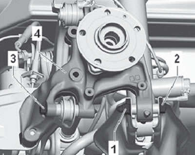
9. Unscrew the mounting screws (1) shown in the figure below.
10. Remove the vehicle height sensor mounting bracket (2) from the rear suspension arm.
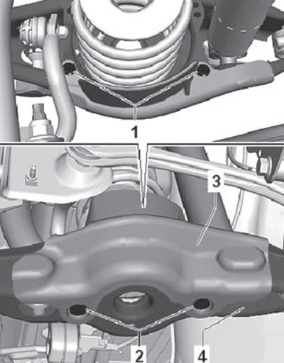
11. Drill out the rivets (1) shown in the figure below.
12. Unscrew the fastening screws (2) of the spring protection (3).
13. Remove the stone guard (3) from the rear suspension lower arm (4) as shown in the figure below.
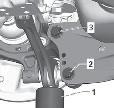
14. Place a special jack under the rear suspension cross rod and load the suspension (1).
15. Unscrew the mounting bolts (2) and (3) shown in the figure below.
16. Remove the jack from under the rear arm.
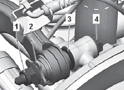
17. Loosen the mounting nut (1) and remove the washer (2) shown in the figure below.
18. Unscrew the mounting bolts (4) shown in the figure below.
19. Remove the washer (3).
20. Loosen the mounting nut (1) and remove the mounting bolt (2) shown in the figure below.
21. Unscrew the mounting bolt (3).
22. Remove the rear wheel axle assembly (4) as shown in the figure below.
Installation
Note:
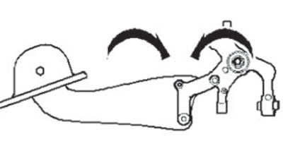
- Tightening the bolts securing the trailing arm to the wheel bearing housing is only possible after all other suspension components have been installed (a spring and shock absorber must be installed). Before tightening the bolts, the suspension must be set to the position corresponding to the maximum rebound travel. Only in this case the longitudinal arm and the wheel bearing housing will be set to the required "arrow" position.
- When performing further work, it is necessary to strictly adhere to the prescribed sequence of actions.
1. Screw in the bolts securing the transverse tie rod, upper transverse arm and lower transverse arm without tightening these bolts completely.
2. Tighten the stabilizer bar mounting bolt to the wheel bearing housing by hand.
3. Screw in the bolts and insert the stabilizer bar into the trailing arm.
4. Tighten the shock absorber mounting bolt.
Note: Tightening the threaded connections securing the suspension components to the wheel bearing housing can only be done after the suspension has been installed in the position corresponding to dimension "a".
5. Install the coil spring.
6. Tighten the tie rod, upper control arm and lower control arm mounting bolts.
7. Tighten the stabilizer bar mounting nut.
8. Tighten the screws.
9. Install the shield.
10. Install the bearing assembly.
11. Install the ABS speed sensor into the wheel bearing housing.
12. Install the brake disc.
13. Install the brake caliper with bracket.
14. Install the wheel and tighten its mounting bolts.
Tightening torques
| Knot | Tightening torque |
| Upper wishbone to wheel bearing housing Use new bolt and nut and tighten to the position corresponding to the curb weight | 130 Nm and turn further by 90° |
| Lower wishbone to wheel bearing housing Use new bolt and nut and tighten to the position corresponding to the curb weight | 90 Nm and turn further by 90° |
| Transverse link to the wheel bearing housing Use new bolt and nut and tighten to the position corresponding to the curb weight | 130 Nm and turn further by 90° |
| Trailing arm to wheel bearing housing Use new bolts. | 90 Nm and turn further by 45° |
| Stabilizer bar link to wheel bearing housing Use new nuts | 40 Nm |
| Shield to the wheel bearing housing | 12 Nm |
| ABS speed sensor to wheel bearing housing | 8 Nm |
| Shock absorber to wheel bearing housing Use a new bolt. | 130 Nm and turn further by 90° |
| Brake disc to wheel bearing housing | 4 Nm |