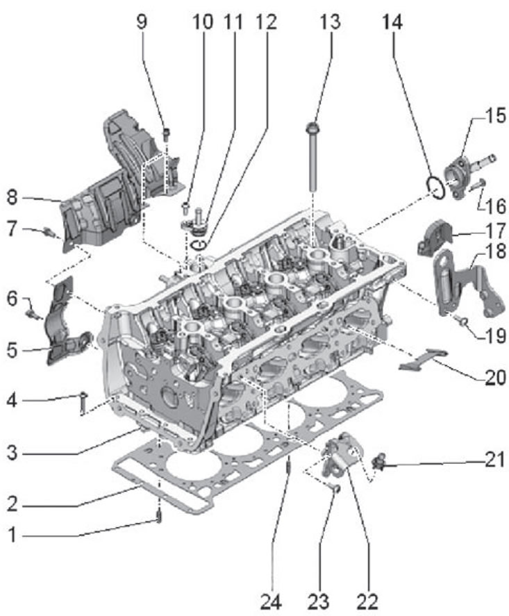
1. Mounting pin; 2. Cylinder head gasket; 3. Cylinder head assembly; 4. Mounting screw; 5. Thermal insulation coating; 6. Fastening screw, tightening torque during installation 9 Nm; 7. Fastening screw, tightening torque during installation 9 Nm; 8. Thermal insulation coating; 9. Fastening screw, tightening torque during installation 9 Nm; 10. Thermal insulation coating; 11. Connecting nipple; 12. Sealing ring; 13. Cylinder head mounting bolt; 14. Sealing ring; 15. Supply nipple; 16. Fastening screw, tightening torque during installation 9 Nm; 17. Support; 18. Mounting eye; 19. Fastening bolt, tightening torque during installation 8 Nm + tighten an additional 90°; 20. Divider plate; 21. Ball joint; 22. Mounting eye; 23. Mounting bolt, tightening torque during installation 8 Nm + tighten additionally by an angle of 90°; 24. Mounting pin
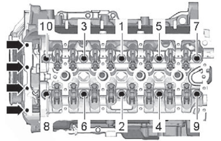
Sequence for unscrewing the cylinder head bolts
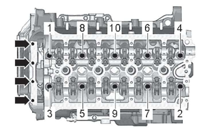
Sequence and tightening torque of cylinder head bolts
Tighten the cylinder head mounting bolts in the sequence shown in the figure below in several steps:
- 1. Tighten the mounting bolts to a torque of 50 Nm.
- 2. Tighten the mounting bolts an additional 90°.
- 3. Tighten the mounting bolts an additional 90°.
- 4. Tighten the mounting screws (arrows) to a tightening torque of 8 Nm.
- 5. Tighten the mounting screws (arrows) an additional 90°.