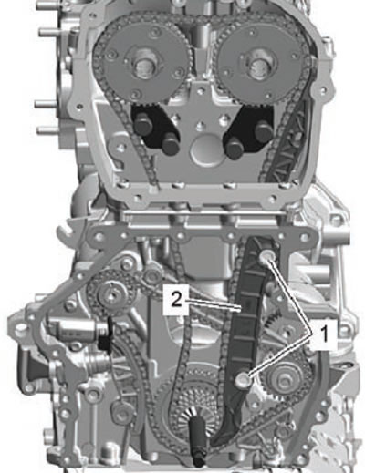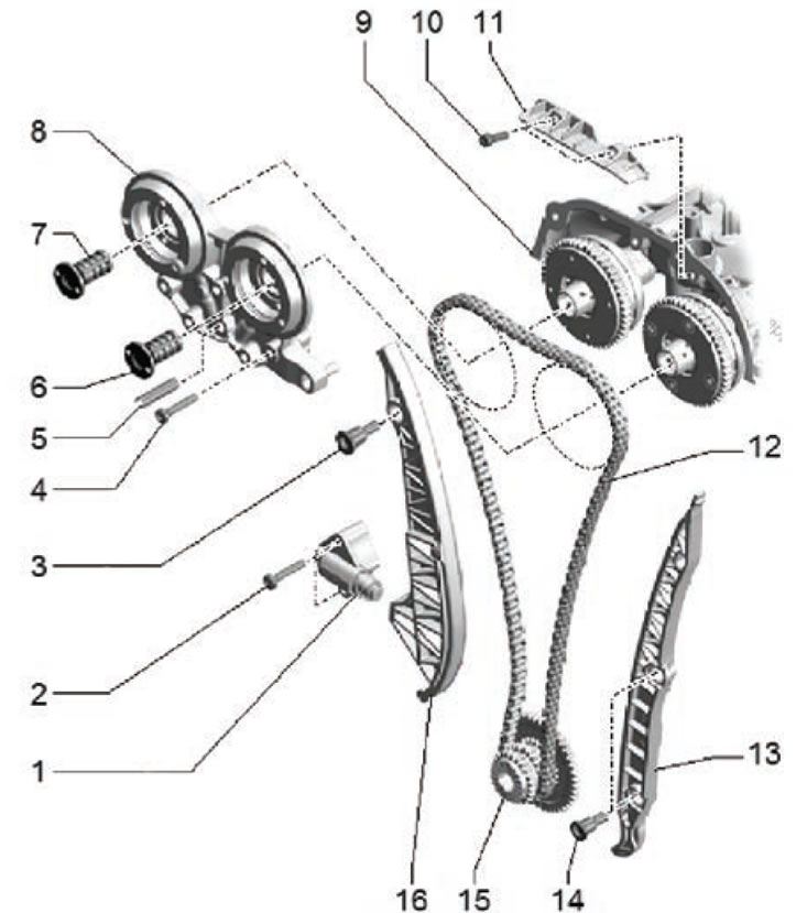
1. Timing chain tensioner; 2. Mounting bolt, tightening torque during installation: 4 Nm + 90 degrees; 3. Guide pin, tightening torque 20 Nm; 4. Mounting bolt; 5. Bushing; 6. Phase shifter control valve, tightening torque 35 Nm; 7. Phase shifter control valve, tightening torque 35 Nm; 8. Support covers; 9. Cylinder head cover; 10. Fastening bolt, tightening torque 9 Nm; 11. Chain guide, upper; 12. Timing chain; 13. Side chain guide; 14. Guide pin; 15. Crankshaft gear; 16. Timing chain tensioner rack
Removal and installation
1. Remove the upper timing chain cover.
2. Remove the lower engine compartment protection.
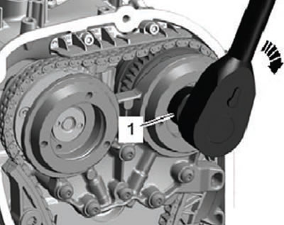
Please note: The phase shifter control valves have left-hand threads.
3. Using a special adapter (T10352/2), unscrew the control valves of the phase shifters of the intake and exhaust camshafts, as shown in the figure below.
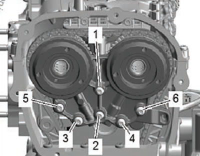
4. Unscrew the mounting screws (arrows) and remove the camshaft phase shifter cover, as shown in the figure below.
5. Turn the crankshaft pulley using the counter support (T10355) to set the piston of the first cylinder to the TDC position.
- The marks (3) on the camshaft sprockets must point upwards.
- The notch (arrow) on the crankshaft pulley (1) must be opposite the mark on the lower timing chain cover (arrow) (5).
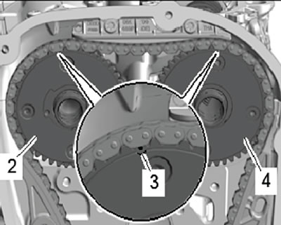
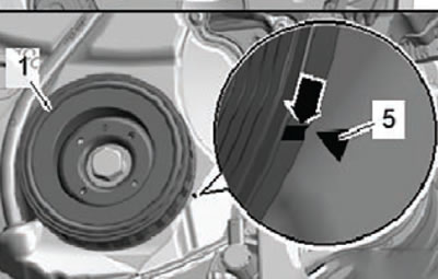
6. Remove the lower timing chain cover (for more details, see the relevant section in this chapter).
7. Unscrew the mounting bolts (arrows) shown in the figure below.
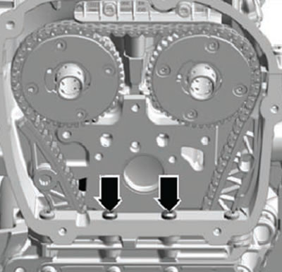
8. Install the special lever (T40243) (arrows) as shown in the figure below.
9. Press on the timing chain tensioner retaining ring (1) and fix it in this position.
(Data Copied from the portal skodabook.ru)
10. Slowly compress the tensioner rack using the special tool (T40243) in the direction of the arrow, as shown in the figure below.
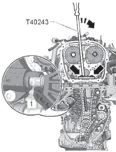
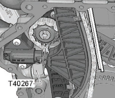
11. Using the special tool (T40267), secure the timing chain tensioner as shown in the figure below.
12. Remove the special tool lever (T40243).
13. Install the camshaft locking tool (T40271/2) on the cylinder head and move it towards the teeth of the camshaft drive sprocket (in the direction of arrow B), as shown in the figure below. Turn the intake camshaft using the special tool (T40266) in the direction of arrow A, as shown in the figure below.
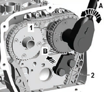
14. Screw the special camshaft locking tool (T40271/1) into the cylinder head.
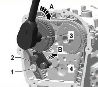
15. Turn the exhaust camshaft using the special tool (T40266) in the direction of arrow A. Loosen the bolt (1) and direct the tensioner rack (2) downwards. Turn the exhaust camshaft sprocket clockwise (A) until the special locking tool (T40271/2) engages the teeth of the gear (C), as shown in the figure below.
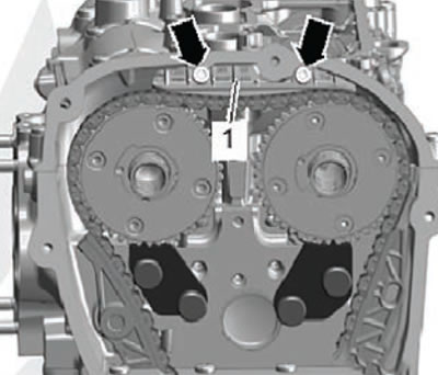
16. Unscrew the mounting screws and remove the timing chain guide rail (1) by pulling it towards you (1), as shown in the figure below.
17. Press the oil pump drive chain tensioner rack in the direction of the arrow, then fix the tensioner in this position by installing the special rod (T40011), as shown in the figure below.
18. Unscrew the mounting bolt (1) and remove the chain tensioner.
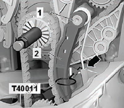
19. Unscrew the mounting bolts (1), then remove the timing chain guide rail (2), as shown in the figure below.