
Wheel speed sensor for ABS
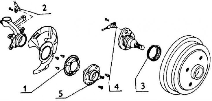
1 - impulse wheel for removing the revolutions of the front wheel; 2 - front wheel speed sensor; 3 - impulse wheel for removing revolutions of the rear wheel; 4 - rear wheel speed sensor; 5 - bolts
Connection diagram of the brake system with ABS
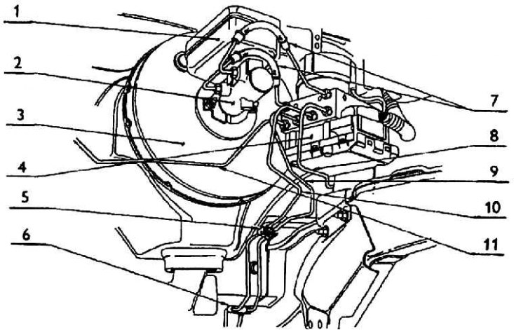
1 - reservoir for liquid; 2 - the main tandem brake cylinder; 3 - vacuum brake booster; 4 - hydraulic and control unit ABS; 5 – a clip of the brake pipeline; 6 – a clip of the brake pipeline; 7 - tube connecting THV with hydraulic and ABS control unit (first and second brake circuit); 8, 9, 10, 11 - pipelines to the brake devices of individual wheels
ABS Hydraulic and Electrical Connection Diagram
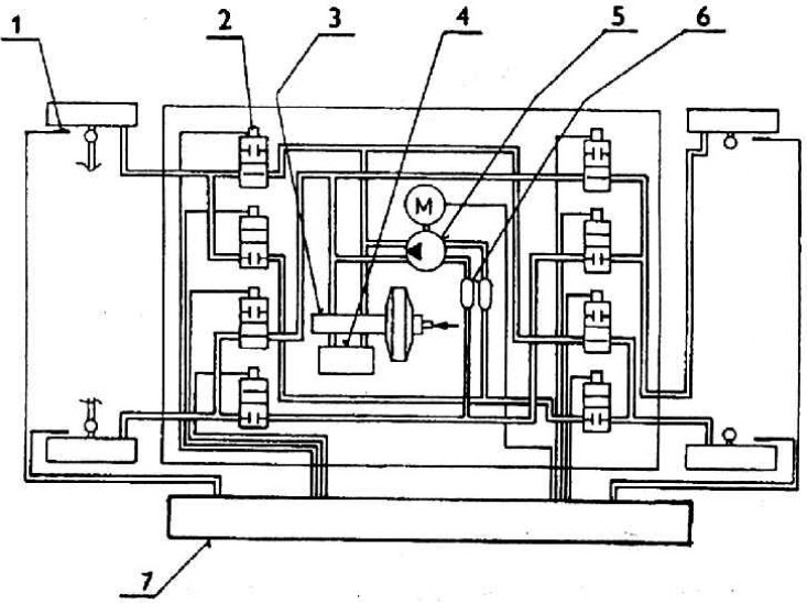
1 – sensor; 2 - solenoid valve; 3 – foot brake tandem cylinder; 4 - brake fluid reservoir; 5 - pump; 6 - tank; 7 - hydraulic and electronic control unit
The installed ABS is an ITT AUTOMOTIVE EUROPE product, type MK 20 I. It is a closed four-channel system, which means that braking control occurs on all four wheels. On the front wheels, the brakes are controlled separately, on the rear wheels according to the select low principle, i.e. with a wheel that is closer to blocking.
At the same time, the second wheel can transmit more lateral force, which guarantees greater vehicle stability.
The action of ABS is as follows: inductive sensors (sensors) constantly monitor the movement of the impulse wheels (in separate wheels of the car) and transmitting the rotation speed information to the ABS control unit. This information is processed and the values of wheel skid, wheel rotation delay and vehicle speed are calculated at the same time.
As soon as the control unit registers a tendency to block at any wheel, it issues a control signal to the solenoid valves that correct the brake fluid pressure in the brake device of the corresponding wheel. This means that when adjusting with ABS, the brake pressure on a given wheel is maintained constant, but if the skid increases, the pressure in the brake device of the wheel is reduced by the ABS pump. This reduces the braking effect and the rotation of the wheel resumes.
Conversely, if the wheel brakes too little, the system increases the pressure and thereby increases the braking effect. The process is repeated in various ways, depending on the mode in which the wheel is located.
If a malfunction occurs in the ABS, the system will automatically disconnect and the vehicle can be braked further in the usual way, as if the ABS was not installed.
The brake system with ABS differs from the system without ABS by the foot brake tandem cylinder and, of course, by the brake lines and hoses.
Before adjusting the ABS or in the event of a failure of the ABS, the braking action on the rear axle wheels is limited by the electric brake force limiter EBV (Elektronischer Bremskraftverteiler), which uses ABS solenoid valves. A vehicle equipped with ABS does not have a load regulator. In the event of a malfunction of the EBV, the pressure limitation on the rear axle brakes does not work and its wheels, compared to the state when the EBV is running, are overbraked.
In the interests of driving safety and the use of ABS, in the event of any malfunction, seek help from a ŠKODA service.