
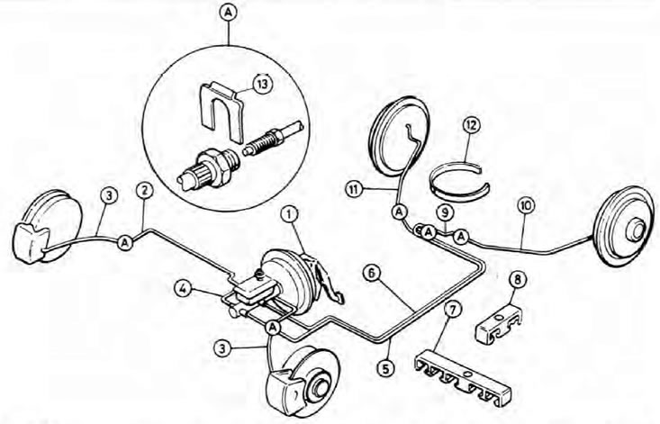
Pic. 9.1. Arrangement of brake system components (Hatchback, Wagon and Van models)
1. Assembling the vacuum booster of the main cylinder; 2. Brake tube; 3. Hose; 4. Brake tube; 5. Brake tube; 6. Brake tube; 7. Bracket; A. Staple; 9. Hose; 10. Brake tube; 11. Brake tube; 12. Plastic tie; 13. Spring clip.
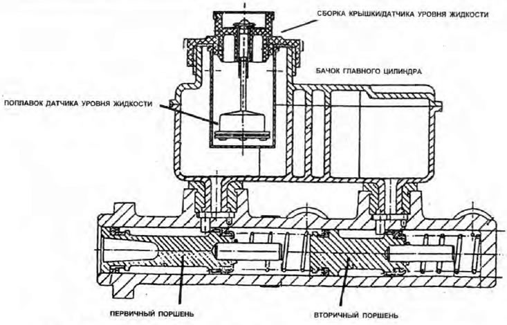
Pic. 9.2. master cylinder (early models) and its nutrient tank in section
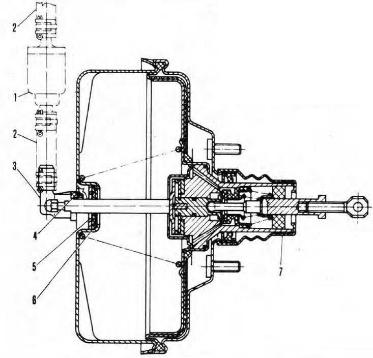
Pic. 9.3. Sectional vacuum booster block
1. Non-return control valve; 2. Hose; 3. Hose coupling; 4. O-ring; 5. Washer; 6. Seal; 7. Rubber boot.
The brake hydraulic system is equipped with an amplifier and is divided into two independent circuits. Each of the circuits controls one of the front and diagonally opposite rear brake assemblies. Front disc brakes, rear drum brakes. The master cylinder and the vacuum booster block to which it is attached are located on the left side of the bulkhead in the engine compartment.
The main cylinder is a tandem type, a system of metal tubes and hoses is connected to it. The primary circuit controls the right front and left rear brakes, and the secondary controls the left front and right rear, respectively. Under normal circumstances, both circuits work in unison. In the event of a failure of one of the circuits, braking will still be effective, albeit at the expense of only two wheels. This will increase the pedal travel.
The amount of hydraulic pressure in the rear brakes is controlled by pressure control valves, which helps prevent the rear wheels from locking during hard braking. On Pickup models, a load-sensing valve is installed, connected by a spring to the rear suspension torsion beam - it regulates the pressure according to the load on the car. All other models use pressure sensitive valves in the master cylinder (one for each loop). Note that the pressure sensitive valves on the Station Wagon and Van models actuate at a higher pressure than the valves used on the Hatchback models, i.e. each specific model must be fitted with the same type of valve of the appropriate type.
The handbrake controls the rear brakes through a lever assembly and cables that run to the support shields of each of the drum brakes.
The instrument panel of the described models has a brake fluid level warning lamp, the circuit of which is closed by a float-type sensor installed in the filler cap of the master cylinder reservoir so that the lamp lights up whenever the fluid level drops to a dangerously low level. In addition, these models are equipped with a handbrake applied indicator lamp activated by a plunger switch located at the base of the handbrake lever.
The vacuum booster unit uses vacuum in the intake manifold (it only happens when the engine is running), to reduce the effort required from the driver to fully depress the brake pedal. The unit transmits this total braking force to the pistons of the master cylinder by means of a push rod connected through a link to the brake pedal. The main component of the amplifier is a sealed metal chamber, divided into two halves by a diaphragm, the bypass channels of the chamber compartments open under the action of a pusher rod. Under normal operating conditions, the pressure in both compartments is less than atmospheric pressure, but when the brake pedal is applied, the rear compartment bypass valve opens and the pressure in it equals atmospheric pressure. The resulting pressure drop forces the diaphragm, and with it the master cylinder primary piston rod, to move forward, transmitting brake force to the master cylinder.
The front brake calipers have a single sliding type piston which will mix the caliper into a mounting bracket rigidly attached to the steering knuckle. Braking performance depends on this ability to slide in the mounting bracket, as well as the condition of the pads, caliper bore walls, piston and seals.
The rear brakes consist of a cast-iron drum attached to the hub and wheel, as well as a support plate, which is mounted on the trailing arm of the rear suspension and carries the pads and the working brake cylinder. The gap between the pads and the drum is adjusted automatically, compensating for the wear of the pad linings.
Note: When servicing any part of the system, work carefully and methodically and be meticulously clean. Replace Component (along with its pair installed on the opposite side of the car), if there is any doubt about its condition. Use only genuine Skoda parts, or at least good quality parts. Take heed of the Asbestos Dust and Brake Fluid Quality Warnings given in this Section. While many companies make brake pads that do not contain asbestos, it is safer to assume that the pads fitted to your vehicle are not «harmless» type and take the precautions described above.
Note: Vehicles manufactured since April 1992 are equipped with 22.2 mm bore master cylinders (instead of previously used cylinders with a diameter of 22.0 mm) and a vacuum booster block with an unregulated rod of the primary piston of the master cylinder; old and modified components can only be used as matched pairs. If any of them are to be replaced, select a component with the appropriate specification for this.