



Front axle - designation of types for individual sub-assemblies
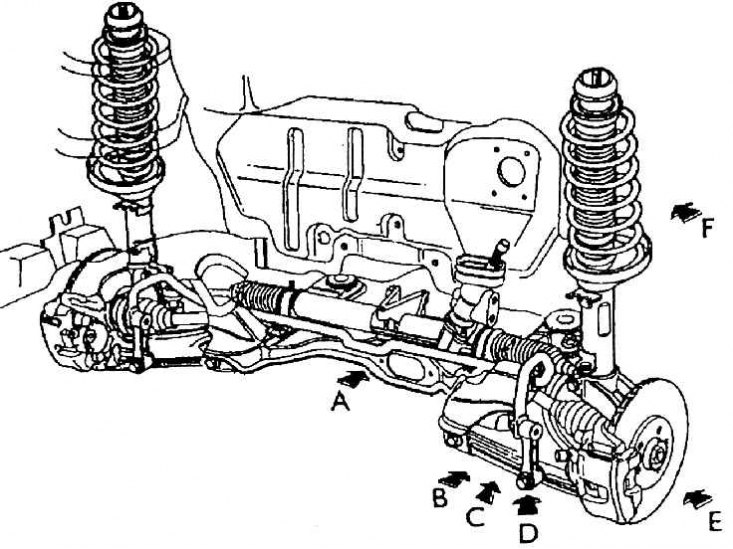
View A – fastening of the steering assembly to the front axle beam
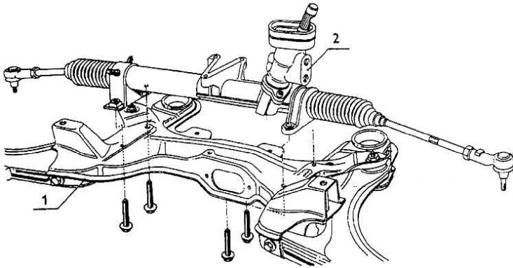
1 – front axle beam; 2 – steering assembly
View B – assembly scan of the steering knuckle assembly, steering rod, propeller shaft and lower rocker arm mount
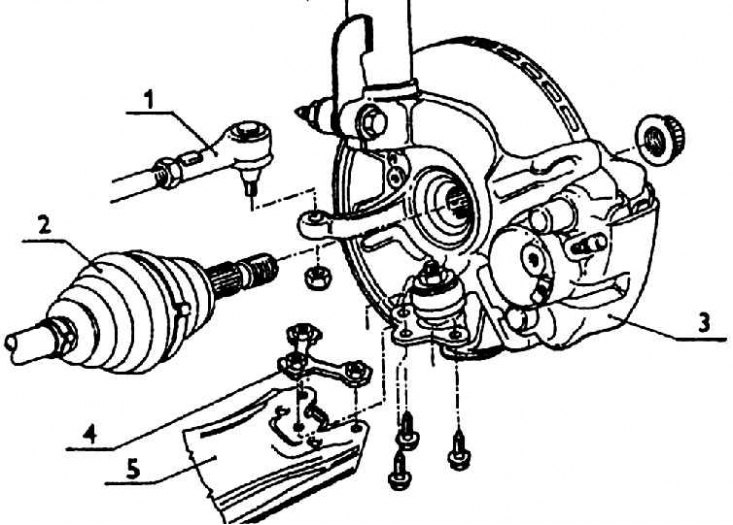
1 – outer joint of the steering rod; 2 – cardan shaft assembly; 3 – steering knuckle assembly; 4 – overlay; 5 – lower rocker arm
View C – fastening the front axle beam to the body

1 – body frame; 2 – front axle beam; 3 – combination bolt; 4 – elastic hinge
View D – mounting the lower arm to the beam
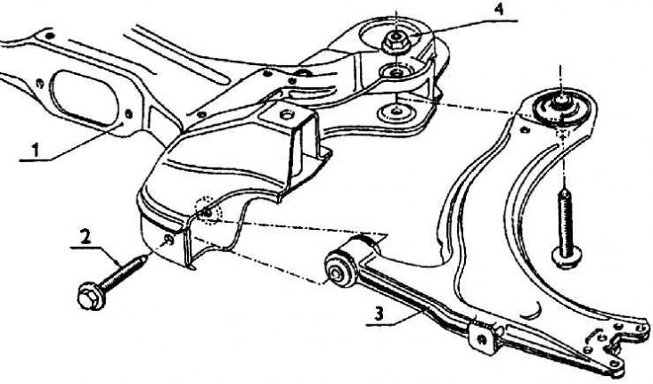
1 – front axle beam; 2 – combination bolt; 3 – rocker arm; 4 – nut with washer
View D – installation of the transverse stabilizer
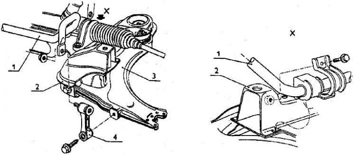
1– stabilizer; 2 – beam; 3 – rocker arm; 4 – stabilizer rod
View E – installation of the front spring assembly to the front wheel hub assembly
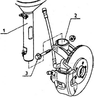
1 – front spring assembly; 2 – Front wheel hub assembly; 3 – spring assembly mounting bolt
View F – fastening the front spring assembly to the body
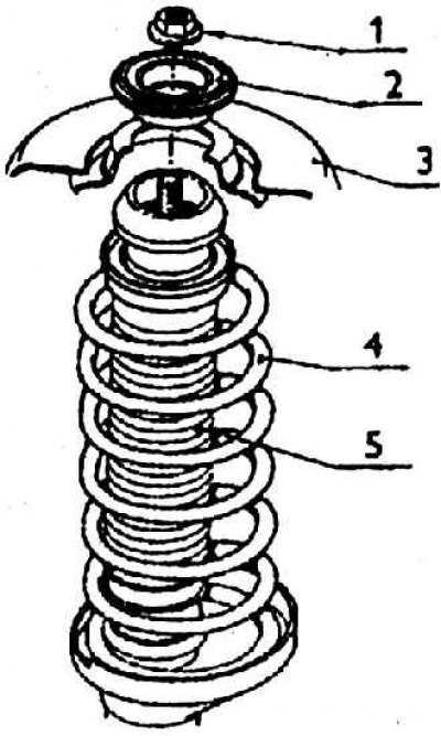
1 – lock nut; 2 – fixing plate; 3 – shock absorber holder in the body; 4 – coil spring; 5 – additional spring
The McPherson type front axle assembly is a mounting unit that, in addition to the front axle itself, i.e. the front beam with swinging consoles, also includes the wheel hubs in assembly, drive shafts, transverse stabilizer, steering assembly, front wheel brakes and elastic units. If some subassemblies are thematically related to other groups (for example, brakes, shock absorbers, etc.), their description will be given in the relevant chapters.
The beam, also called the auxiliary frame (see Fig. View D - mounting the lower arm to the beam), is a welded structure made of sheet metal stamping, attached to the body (in places above the front landing of the rocker arms) two bolts and at the rear similarly with two combined bolts through an elastic hinge. The bolts are oriented vertically (see Fig. View C - fastening the front axle beam to the body).
On the sides of the beam, swinging levers are suspended in elastic hinges. The front mounting of the lever is horizontal, diagonally relative to the vehicle's axis. The rear mounting is vertically positioned with a bolt. Consequently, the swinging movement of the levers is possible only due to the rubber elements of the hinges (see Fig. View D - mounting the lower lever to the beam).
On the front side of the levers there are panels with threads for mounting the vertical rod stabilizer rods. The stabilizer rod itself is screwed to the beam in rubber bushings (see Fig. View D - mounting the transverse stabilizer).
Four bolts inserted from below secure two steering control assembly clamps to the beam (see Fig. View A – securing the steering control assembly to the front axle beam).
At the outer ends of the rocker arms there are three oval holes for fastening the ball joint holders of the front wheel hub. The flange of the wheel hub is attached to the arm from below, on its upper surface there is a cover plate with welded nuts for three bolts inserted from below.
By moving it in the oval holes, you can slightly change the camber of the wheels (see Fig. View B - installation layout of the steering knuckle assembly, steering rod, cardan shaft and lower rocker arm mount). At the top, the lower end of the spring assembly is inserted into the cartridge. The spring assembly and the mentioned ball pin allow the wheel hub (steering knuckle) to rotate or perform the function of a classic kingpin.