



Aluminum alloy cylinder block
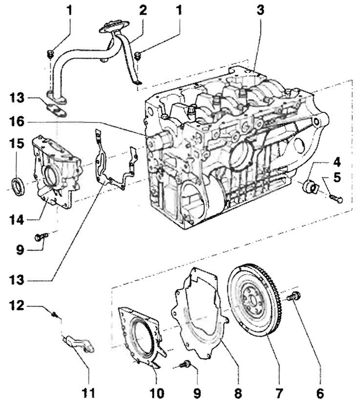
1 - 10 Nm; 2 - Inlet manifold; 3 - Cylinder block; 4 - Knock sensor; 5 - 20 Nm, the tightening torque value affects the operation of the knock sensor; 6 - 60 Nm + turn an additional 1/4 turn (90°), replace; 7 - Flywheel; 8 - Intermediate sheet, must be installed on fitting bushings; 9 - 12 Nm, replace; 10 - Replace the flange sealing gasket with the pulse wheel and sealing ring only with a set with a sealing ring and pulse wheel; 11 - Speed sensor; 12 - 10 Nm; 13 - Seal, replace; 14 - Oil pump, replace only as a set, must be installed on fitting bushings; 15 - O-ring, replace; 16 - Before installing the oil pump, lubricate the hinge element with oil
Disassembly and assembly of the piston and connecting rod
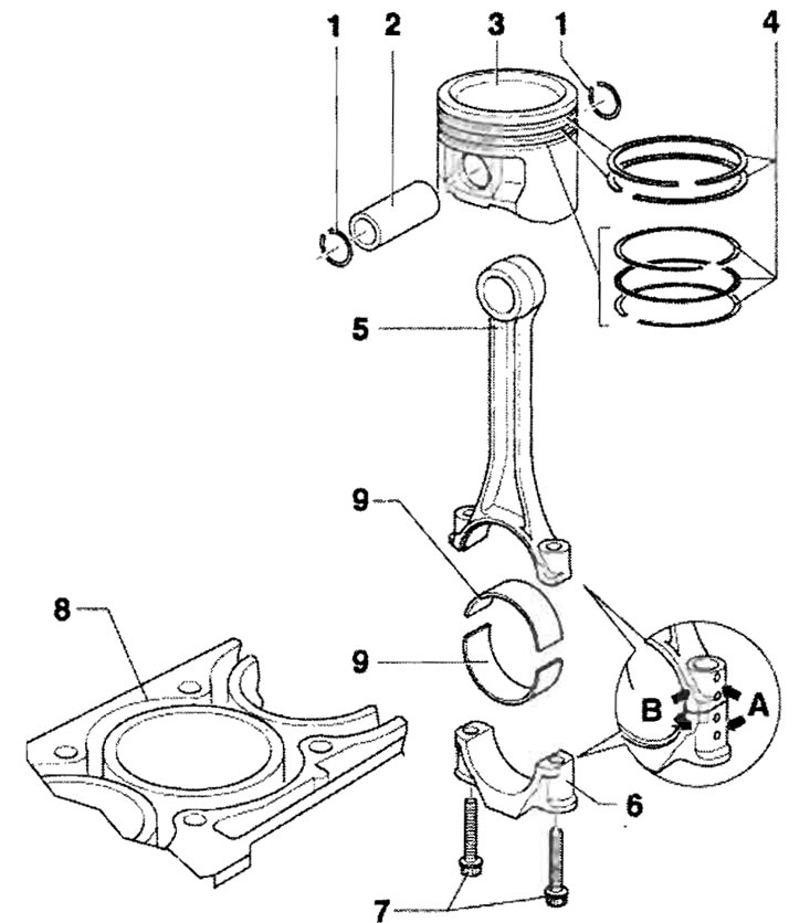
1 - Retaining ring; 2 - Piston pin, in case of tight movement, heat the piston to a temperature of approx. 60°C; 3 - Piston, mark the position for assembly and belonging to the cylinder liner, the arrow on the bottom of the piston points towards the pulley, piston diameter - 76.47 mm; 4 - Piston rings, mutually shift the locks by 120°, remove and install using piston ring pliers. Removal and installation of three-element oil scraper piston rings should be done manually, the marking -TOP- should be directed towards the piston bottom; 5 - Connecting rod, always replace as a complete set, mark the affiliation with cylinder liner "A", assembly position: marks "B" facing the pulley, axial guidance through the piston; 6 - Connecting rod cap, the cap fits against the connecting rod separated by a break in only one position and only against the corresponding connecting rod; 7 - Connecting rod bolt, M7x0.75: 20 Nm + turn an additional 1/4 turn (90°), M8x1: 30 Nm + turn an additional 1/4 turn (90°), replace, lubricate the threads and mating surface with oil; 8 - Cylinder block, cylinder diameter = 76.51 mm; 9 - Bearing shell, do not mix up already used bearing shells (mark), install bearing shells centered, axial clearance for a new part: 0.10...0.35 mm; wear limit: 0.40 mm