
Note.
- Necessary special devices, control and measuring devices, as well as auxiliary means:
- Setting tool -T10374-.
- Curve ruler -T40100-.
- Adhesive -AMV 195 KD1 01-.
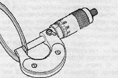
- Digital depth gauge.
Note.
- Clutch shim "K1" is inserted on a large bearing, and the shim for the clutch "K2" inserted under the small bearing.
- The position of the engagement lever must be adjusted if the clutch or clutch actuator has been replaced.
- The control also includes a fastener.
- If the mentioned parts are only removed and reinstalled, then there is no need for adjustment.
Note.
- Use only tools in perfect condition.
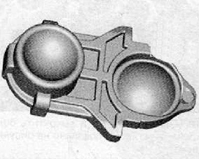
- The clutch housing flange must not be uneven. This ensures that the ruler fits correctly.
- Mechatronics built in.
Short description
The position of the clutch bearing is comparable to the clutch clearance of a manual transmission. In the DSG-OAM automatic transmission, there are approvals for the gearbox engagement system and for the gearbox itself. Tolerances are also available inside the double (double) clutch. In the case of regulation, these tolerances must be evaluated separately
The following description first describes how the «on the side of the gearbox" all necessary dimensions so that a suitable shim can be determined. The tolerance on the gearbox side and the tolerance in the clutch determine the thickness of the shim.
First you need to determine the size "IN". This dimension is required for both clutches «K1» and «K2».
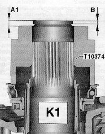
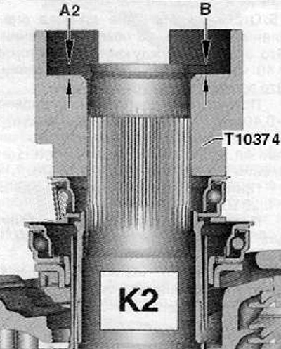
Then, for each clutch, the size is determined "A". The figures below show the measurement locations.
«K1»
«K2»
Note. The following work steps must be carried out exactly and in sequence.
Setting
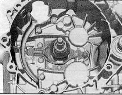
1. Install the clutch parts up to the larger clutch release fork as shown in the figure below.
Note. Do not install a small release bearing and do not insert a shim.
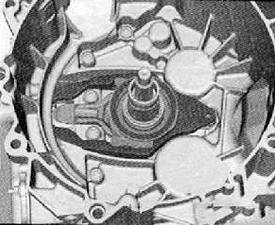
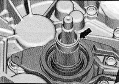
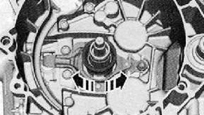
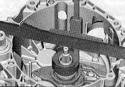
2. Install the circlip of the outer drive shaft (arrow), as shown in the figure below.
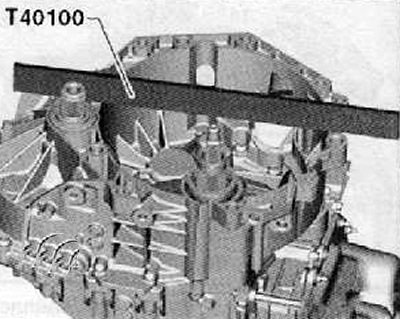
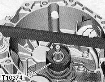
3. Put a special ruler on the clutch housing flange (Т40100), as shown in the figure below.
Note. Ensure ruler location (Т40100) during the next measurements in this position. Do not move or delete.
4. put the digital depth gauge (A) on the outer drive shaft (IN), as shown in the figure below. Set the depth gauge to zero.
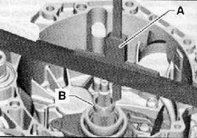
5. Measure the distance from the retaining ring.
Mark the result, name it «IN».
Note. Size "IN" should be measured again at the opposite location.
Note.
- Do not measure at the lock of the ring.
- The whole point is that the lock can be wrung out, which will affect the measurements.
6. Remove the circlip again.
Note. This ring can no longer be installed!
7. Calculate the average value from both measurement results.
This size "IN" needed for the following calculations.
In the following exemplary calculations "IN" = 2.96 mm (example). Size "IN" serves only for this example; its meaning may be different for other gearboxes.
In view of the fact that there are two clutches, two steps are then performed for adjustment.
Each measurement requires different preparatory measures and several calculations.
8. Determine the shim size of the large clutch mounting foot «K1».
Attention. Do not install any shim!
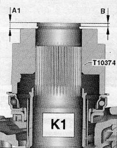
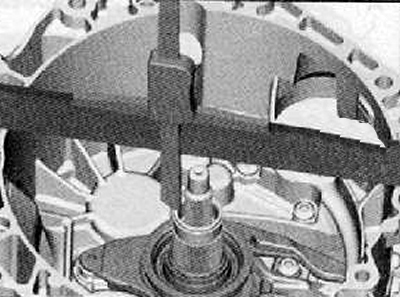
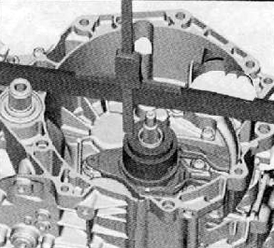
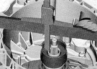
9. Place the setting tool (Т10374) on the large clutch release bearing.
10. Press on the setting tool (Т10374), by turning it. Thus, it is possible to observe the rotation of the engagement clutch bearing. So, also an installation device (Т10374) «is sitting» properly on the bearing.
11. Place the digital depth gauge on top of the outer drive shaft.
Note. Ruler (Т40100) already placed on top of the clutch housing flange.
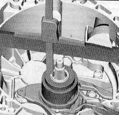
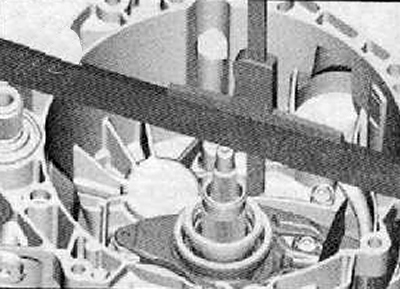
12. Depth gauge should measure the distance from the end of the shaft to the installation tool (Т10374), as shown in the figure below.
13. To make the measurement as accurate as possible, install the digital depth gauge twice, in opposite places. In this way, a much more accurate result is obtained, since the inaccuracy caused by oscillation on the clutch bearing is reduced to a minimum.
14. Both measurements in relation to the setting tool (Т10374) average should be calculated. This value should be labeled and labeled "A1".
Example:
Size "A1" = (2,61+2,81) /2 = 2,71
"A1" = 2.71 mm
Next calculation:
"A1" minus "IN" plus mounting fixture height (Т10374) = Depth of clutch engagement bearing 1.
Mounting fixture height (Т10374) the same all the time. It is - 51.81 mm.
Calculation example:
2.71 mm - 2.96 mm + 51.81 mm = 51.56 mm.
The meaning of how deep the engagement clutch bearing actually sits in the gearbox has now been determined.
It is required that each gearbox has a bearing depth of 50.08 mm.
From this true size, the required size of 50.08 mm is subtracted. This results in the true clutch clearance 1.
Revealed value (example: 51.56 mm) minus required value = clutch clearance.
Calculation example:
51.56 mm - 50.08 mm = clutch clearance 1 = 1.48 mm.
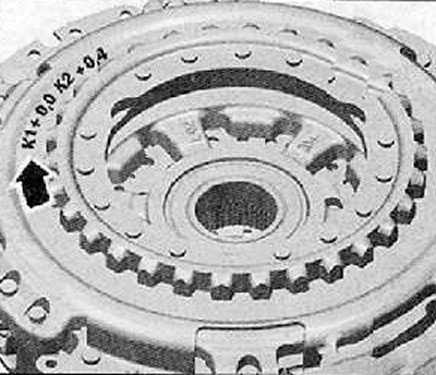
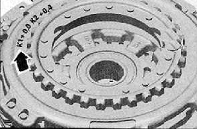
15. Read off the clutch tolerance -arrow- on the new clutch. This value is between minus 0.40 and plus 0.40 mm and is marked on the clutch. This value should be noted.
Example 1: Clutch shown "-0.40mm".
Last calculation for «K1»: Calculated clearance minus clutch values 1 = 1.48 mm - 0.40 = 1.08 mm.
Example 2: Clutch shown "+0.20 mm".
Last calculation for «K1» looks like this: 1.48 mm + 0.20 = 1.68 mm.
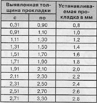
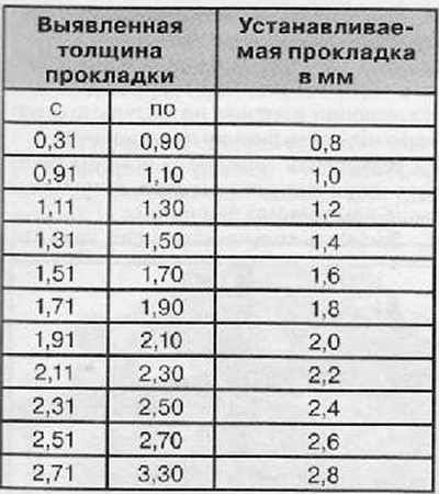
16. Having selected the correct gasket according to the table, install it.
 |  |
Attention. Later, only this one shim should be inserted, not two shims.
17. Continue clutch adjustment «K2».
Determination of the adjusting shim of the small clutch release fork «K2»
18. Install only the small release bearing.
Attention. Do not install any shim.
Note. The small clutch release bearing can only be positioned in one single position due to the 4 grooves.
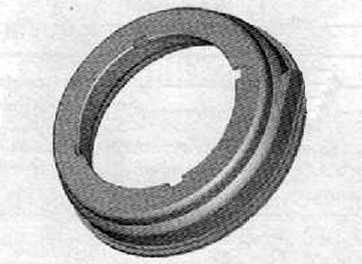
19. By turning, check whether the small clutch release bearing is installed correctly and whether the grooves are seated correctly.
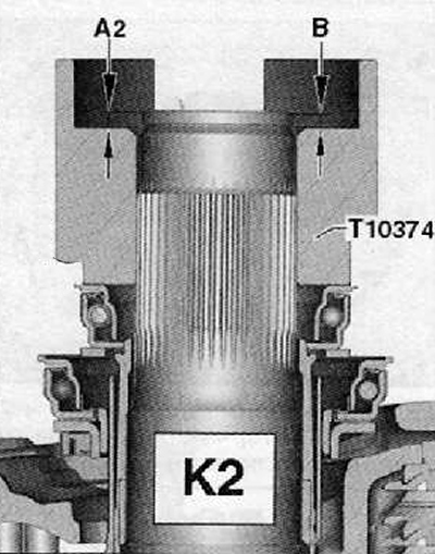
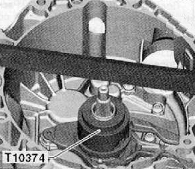
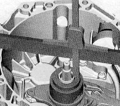
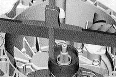
20. Place the setting tool (Т10374) large hole up onto the small bearing, as shown in the figure below.
21. Place the digital depth gauge on top of the outer drive shaft as shown in the figure below.
22. Reset the depth gauge to zero.
23. Depth gauge should measure the distance from the end of the shaft to the installation tool (Т10374), as shown in the figure below.
24. In order to make the measurement as accurate as possible, the digital depth gauge should be installed twice, in opposite places. Thus, a much more accurate result is obtained, since the inaccuracy caused by oscillation on the clutch bearing is reduced to a minimum.
25. Both measurements in relation to the setting tool (Т10374) average should be calculated. This value should be labeled and labeled «A2».
Example:
Size "A2" = (2,50 + 2,54) /2 = 2,52
"A2" = 2.52 mm
Next calculation:
"A2" minus "IN" plus height of setting tool -T10374- = depth of clutch bearing 2.
The height of the setting tool -T10374 is the same all the time. Inside it is: 36.20 mm.
Calculation example:
2.52 mm - 2.96 mm + 36.20 mm = 35.76 mm.
Now the significance of how deep the engagement clutch bearing actually sits in the gearbox has been revealed.
It is required that each gearbox has a bearing depth of 34.35 mm
The required size is subtracted from this true size "34.35 mm". This results in the true clutch clearance 2.
Revealed value (example: 35.76 mm) minus required value = clutch clearance.
Calculation example:
35.76 mm - "34.35 mm" = clutch clearance 2= 1.41 mm.
Now it is necessary to include in the calculation the tolerance in the double (double) clutch.
Read off the clutch tolerance -arrow- on the new clutch.
This value is between minus 0.40 and plus 0.40 mm and is marked on the clutch.
This value should be noted.
Example 1: on the clutch is shown "-0.40mm".
Last calculation for «K2»: «Calculated clearance» minus «values from clutch 2» = 1.41 mm - 0.40 - 1.01 mm.
Example 2: Clutch shown "+0.20 mm".
Last calculation for «K2» looks like this: 1.41 mm + 0.20 = 1.61 mm.
26. Select the correct gasket from the table.
 |  |
Note. Among the supplied gaskets, you should choose the one that you need.
Attention. Later, only this 1 shim should be inserted, not 2 shims.