



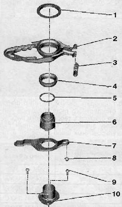
1. Adjusting washer for "K1"
2. Large clutch release fork "K1"
3. Hinge
4. Small clutch release bearing "K2"
5. Adjusting washer for "K2"
6. Guide bushing, upper part
7. Small clutch release fork "K2"
8. Ball joint
9. Fastening screw, tightening torque 8 Nm + turn 90° degrees
10. Guide bushing, lower part.
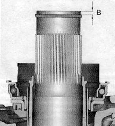
First of all, you need to determine the size "B", shown in the figure below.
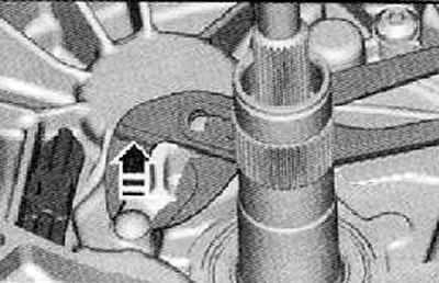
1. Using special pliers, remove the ball joint as shown in the figure below.
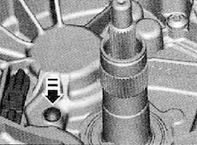
2. Install the new ball joint as shown in the figure below.
Note: Press down on the ball joint by hand to install it, if necessary, gently hit it several times with a rubber mallet.
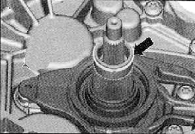
3. Install the old snap ring onto the gearbox shaft as shown in the figure below.
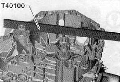
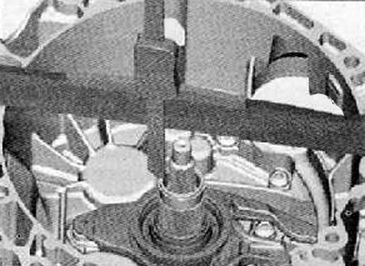
4. Install a special ruler (T40100) on the clutch crater, as shown in the figure below.
Note: Ensure that the ruler is installed in one position and prevent it from moving when performing any operations.
5. Install the depth gauge with dial indicator (A) on the ruler. Install the depth gauge plate on the shaft (B) as shown in the figure below.
6. Set the dial indicator to zero.
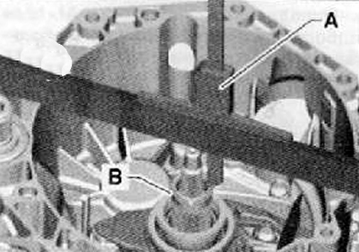
7. Measure the distance to the retaining ring.
8. Mark the obtained result as "B1", for example: size "B1" = 2.62 mm.
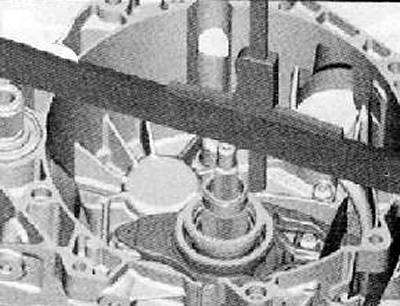
9. Repeat the measurement of distance "B" on the opposite side.
10. Write down the obtained result as "B2", for example: size "B2" = 2.58 mm.
Note: Do not measure on the locking ring. The ring may loosen over time, which will affect the accuracy of the measurement.
11. Calculate the arithmetic mean of the two values obtained above.
"B" = (81 + B2)/2 = 2.60 mm
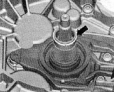
12. Remove the retaining ring from the gearbox shaft as shown in the figure below.
Note: This ring must be replaced with a new one during installation.
Determine the distance "A1" to select the adjusting washer for the larger clutch release fork "K1".
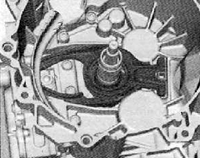
1. Install the large clutch release fork into the clutch housing as shown in the figure below.
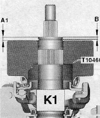
2. Install the special tool (T10466) onto the larger release bearing as shown in the figure below.
3. Press with your hand and turn the special tool at the same time. Check the rotation of the release bearing. Install the special tool properly.
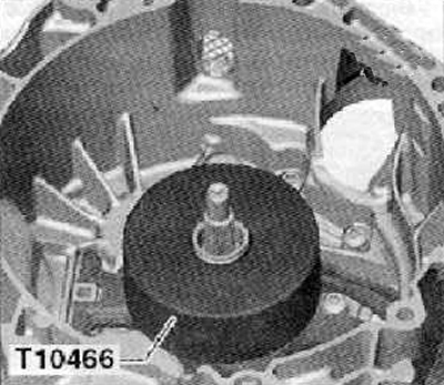
4. Install a depth gauge with a dial indicator on the top of the transmission input shaft as shown in the figure below. Set the dial indicator to zero.
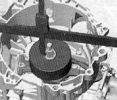
5. Measure the distance from the gearbox shaft to the special tool (T10466), as shown in the figure below.
[Information copied from the resource www.SKODABOOK.ru]
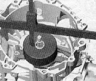
6. Repeat the above measurement on the opposite side of the special device, as shown in the figure below. This is necessary to eliminate the influence of the bearing runout on the measurement results.
7. Calculate the arithmetic mean of the two values obtained in the measurements described above.
8. Write the resulting number as "A1".
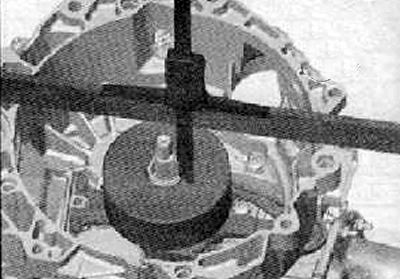
The difference between "A1" and "B" is the depth of the clutch release bearing "K1".
9. Continue the calculation. To do this, you need to pay attention to the housing of the new clutch and read the inscription shown in the figure below. In the example below, you can see the inscription "K1" + 0.0. For the final calculation, which will allow you to select the adjusting washer, you need to add the value that is written to the obtained value "K1". Example: if "K1" = 2.32 mm, then the thickness of the adjusting washer: 2.32 + 0.0 = 2.32.
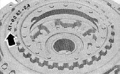
10. Select an adjusting washer from the standard series with a thickness closest to the theoretically calculated value. The standard series of adjusting washers is shown in the table below.
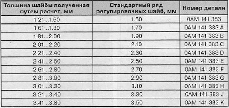
Attention: Only one adjusting washer should be installed, no more.
Note: The adjusting washer is installed during final assembly of the clutch.