
Note.
- Necessary special devices, control and measuring devices, as well as auxiliary means:
- Puller -T10373-.
- Puller -T10323-.
- Pressure piece -T10368-.
- Pressure piece -T10376-.
- Adhesive -AMV 195 KD1 01-.
- Do not lubricate anything with oil or grease!
Note.
- Clutch shim «K1» is inserted on a large bearing, and the shim for the clutch «K2» inserted under the small bearing.
- Before proceeding with the installation of the clutch, it is necessary to adjust the position of the clutch bearings «K1» and «K2».
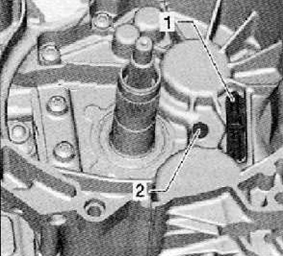
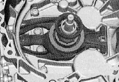
1. Installing the thrust bearing of the selector forks (1) and ball joint (2), as shown in the figure below. Check for correct installation.
Note.
- New clutch release fork «K2» Supplied with top and bottom guide bushing in transport position.
- It is necessary to install the guide sleeve in the normal mounting position.
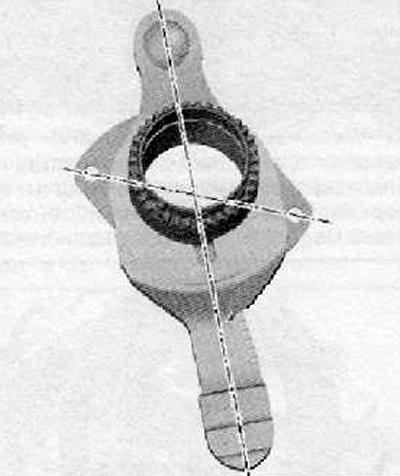
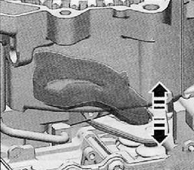
2. Fix the upper part of the guide sleeve of the release fork by hand.
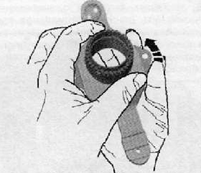
3. Turn the lower part of the guide bush in the direction of the arrow until the clutch starts to move freely, as shown in the figure below.
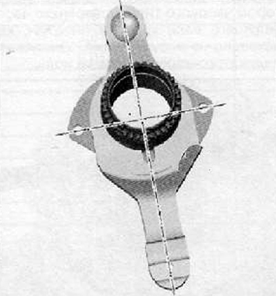
4. In the working position, the cuts on the bottom of the guide sleeve lie on the same axis as the side holes of the release fork, as shown in the figure below, and the sleeve moves freely in both directions.
5. Install the small release fork with the lower and upper parts of the guide sleeve into the clutch housing. as shown in the picture below. Install and tighten the release fork mounting screws to the required torque.
Attention. All parts of the clutch release mechanism must be dry and clean. Eliminate the ingress of oil products on the surfaces of the clutch release elements, as well as on the friction surfaces of the clutches.
6. Install the large clutch release fork with shims «K1» and «K2», as shown in the figure below.
Note. The adjusting washer of the larger release fork is installed with a convex surface down on the larger release bearing; adjusting washer of the small clutch release fork «K2» installed under the small release bearing.
Attention. The small release bearing has eight guide grooves, as well as the shim, so it only fits in one position.
7. Install the small release bearing.
8. Gently turn the release bearing to make sure it is properly installed.
9. Check and make sure that both release forks are correctly installed.
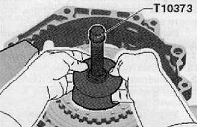
10. Unscrew the puller spindle (T1073).
11. Install the clutch. Clutch with puller (Т10373) should be inserted into the gearbox as shown in the figure below.
12. The lead screw must first be turned back.
Note. The clutch is self-adjusting. The jolts may show up negatively on the tuner. Therefore, you can not drop the clutch. Even when installing the clutch, the clutch must not be dropped into the gearbox.
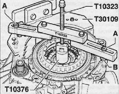
13. Install puller (Т10323) so that it is in a position parallel to the flange of the clutch housing.
14. Align the distances, e.g. using washers (IN) with a total thickness of 15 mm.
15. Attach the puller (Т10323) with screws (A), as shown in the figure below.
Note. screws (A) should be secured with nuts.
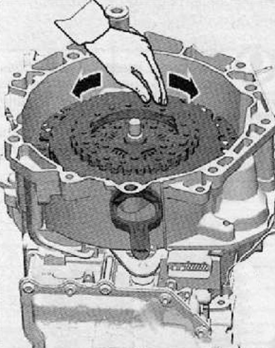
16. The clutch should be pressed down with the lead screw.
Note. When pressing, place your hand on the clutch. Feels like a light bite. Seizing means that the clutch is pressed into its correct position. In this way, you should determine the moment when the clutch is pressed in to the stop. The clutch is pressed in to the stop if it is possible to put on the retaining ring.
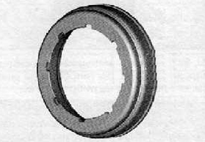
Note. Retaining ring assembly position: Retaining ring lock on top.
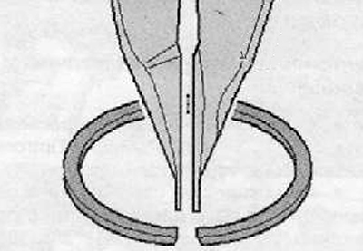
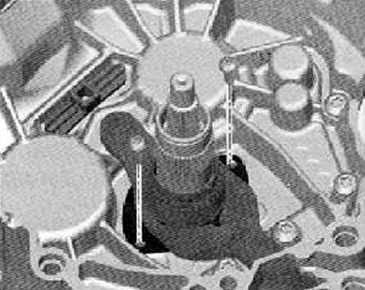
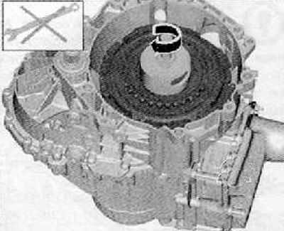
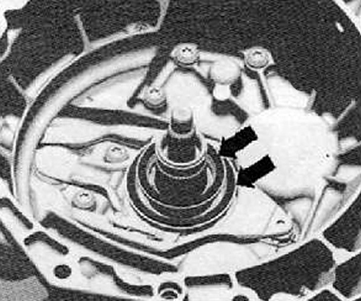
17. Install a new retaining ring (arrow), as shown in the figure below.
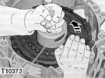
18. This same clutch has already found its position for assembly, you should turn the clutch against the puller by hand, as shown in the figure below. The clutch should only be turned by hand, and no tool should be used.
Note.
- Turn by hand only. Thus, the clutch slips against the retaining ring. Do not use any other tool.
- As a result of pressing, the clutch is installed at the bottom on the drive shaft. The clutch should be pulled upwards only to the extent that it touches the retaining ring.
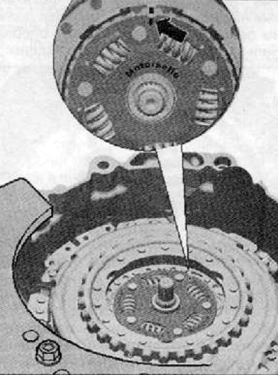
19. Install the hub shown in the figure below.
Note.
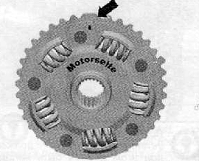
- The hub has one large tooth, so it can only be installed in one single position.
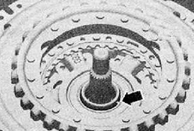
- On the side of the motor, the large tooth is marked (arrow), as shown in the figure below.
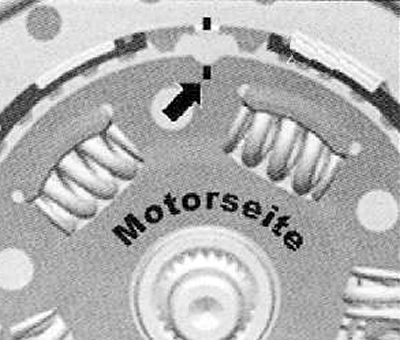
20. Install the hub with the mark on the large tooth so that it matches the mark on the drive disc (arrow), as shown in the figure below.
21. Install the hub circlip (arrow), shown in the figure below. Fitting Position: The ring lock must point towards the lug on the clutch.
22. Turning the clutch by hand, observe the small engagement lever while turning.
Note.
- The setting lever must remain stationary. They can't move up and down.
- If the setting lever moves up and down, this means that the adjusting lever is not in its bearings.
In this case, the clutch must be removed again.
23. Visually check shims (arrows), shown in the figure below. Gaskets must lie correctly in their bearings. They cannot be damaged.
24. After removing the plugs, put on both covers of the tubes to remove air again (arrows), as shown in the figure below. After installing the gearbox, it is necessary to carry out with the help of special equipment the installation in its original position.