
Removing
Note.
- Necessary special devices, control and measuring devices, as well as auxiliary means:
- Mounting lever -T10407-.
- Vehicle diagnostic, measuring and information system -VAS-.
- Collecting bath -VAS 6208-.
Safety note for mechatronics of manual gearbox -J743-.
- Observe the instructions for the DSG automatic transmission.
- In order to be able to remove the mechatronics, sufficient clearance must be provided in front of the gearbox. Some vehicles require the removal of parts that are not directly connected to the transmission. If necessary, it is also necessary to remove the holders located on the screws of the mechatronics cover.
- After disconnecting and then connecting the wire connecting the battery terminal to ground (corps) vehicle, additional work needs to be done.
- The mechatronics remain filled with oil.
1. Move the selector lever to position «R».
Note. Before proceeding with the actual extraction of mechatronics, it is necessary to perform, using a tester, the basic setting of the neutral position of the gearbox.
2. Select the controlled functions and then select the basic neutral position.
3. Remove the air filter (see the relevant section in chapter Intake and exhaust system).
4. Remove the battery and battery holder.
5. Unlock the plug connector on the mechatronics by pulling in the direction of the arrow as shown in the figure below and disconnect the plug connector.
6. After removing the cover from the bleed tube, plug it with a suitable plug so that no oil can escape
Attention. After opening the surge tank, hot steam may escape. After closing the cork with a rag, carefully open it.
7. If the engine is warm, then the cooling system is under pressure. Before disconnecting the coolant hoses, loosen the surge tank cap carefully to relieve the pressure first.
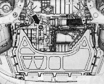
8. Remove the lower engine cover.
9. Remove the charge air hose from the charge air cooler at the bottom left and from the charge air pipe.
Note. Seal the opening of the charge air cooler so that coolant cannot enter it.
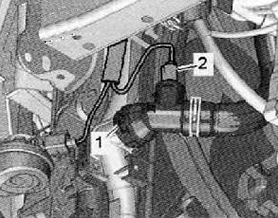
10. Disconnect plug connector (2) From coolant temperature sender - radiator outlet -G83-.
11. Substitute a container to collect liquid (VAS 6208) under the radiator.
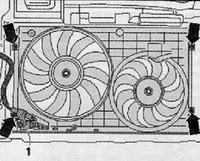
12. Remove the coolant hose from the bottom of the cooler (1), for which you need to lift the retaining clip.

13. Disconnect plug connectors (1) cooler fans on the bottom of the fan shroud.
14. Unscrewing the fastening screws (arrows), as shown in the figure below. Remove the fan shroud with the fans pointing downwards.
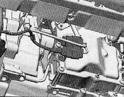
15. Remove the electrical wires from the holder in front of the mechatronics, tie them up.
16. Remove the holder from the mechatronics.
17. Place a receiving bath under the gearbox.
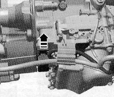
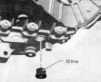
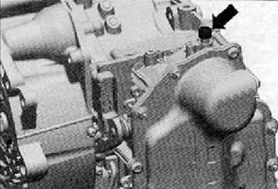
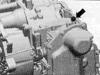
18. Unscrew the oil drain plug (arrow) on the gearbox as shown in the figure below.
19. Let the oil flow out.
20. Reinstall the oil drain plug. Tighten the plug with a tightening torque of 30 Nm.
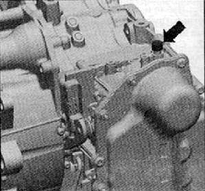
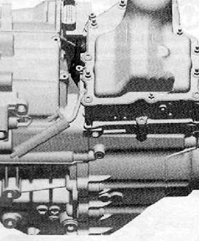
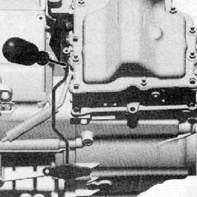
21. Remove all holders from the gearbox as shown in the figure below.
22. Using a screwdriver, carefully unlock the speed sender on the gearbox input shaft -G182- and pull it out of the crankcase in the direction of the arrow as shown in the figure below.
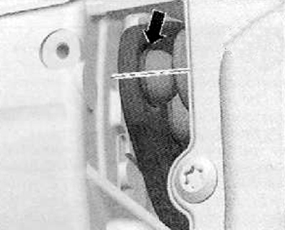
23. Now both clutch control levers should be released from the mechatronics using the mounting lever (10407). Otherwise, the mechatronics lever would sit on the pushers and it would be impossible to remove the mechatronics.
24. For locking, insert a mounting lever into the space between both clutch control levers and the gearbox housing (Т10407), as shown in the figure below.
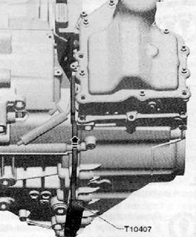
Note. Mounting lever (Т10407) should lie on the entire surface «back side» to the gearbox housing and the spline must be flush with the recess in the housing.
Note. The crankcase recess and the slot on the lever must be at the same level. Do not insert the mounting lever (Т10407) all the way.
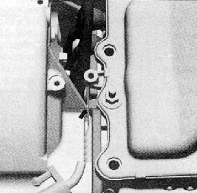
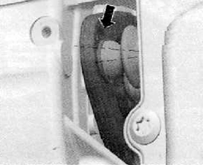
25. Rotate the mounting lever (Т10407) towards (arrows) to the left, as shown in the figure below, thus pressing the gear levers away from the pushers.
Note. Do not remove the mounting lever (Т10407).
26. If necessary, press the mounting lever (Т10407) screwdriver against the gearbox, causing both clutch levers to be pushed away from the mechatronics.
Note. In this case, the rubber cuffs of the clutch regulators must not be damaged.
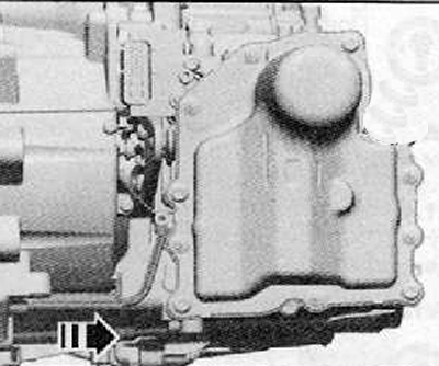
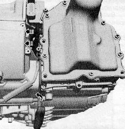
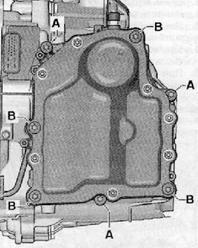
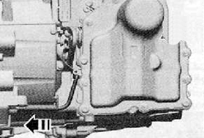
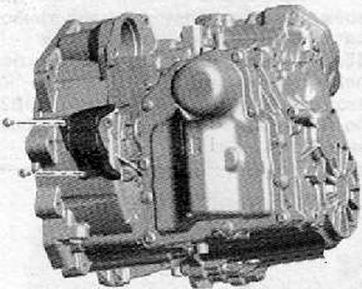
27. Unscrew the long fixing screws crosswise (IN) (4 pieces, M8x90), shown in the figure below.
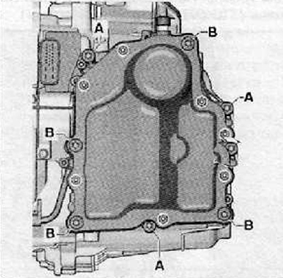
28. Unscrew the remaining fastening screws crosswise (A) (3 pieces, M8x35).
Note.
- Do not remove more than 7 screws! These are 4 long and 3 short screws.
- Do not loosen the mechatronics cover screws.
- The removed mechatronics must be set aside in such a way that no oil can escape through the bleed hole.
- Leaked oil cannot be refilled.
29. Touch the mass with your bare hand (corps) car; as a result of the above, an electrostatic charge is discharged.
Attention.
- The mechatronics of the manual gearbox -J743- may only be touched or removed after the electrostatic charge has been eliminated by touching a grounded object with bare hands, e.g. weight (corps) car.
- Do not touch the contacts in the gearbox connector with your hands, as the electrostatic charge can destroy the control unit and thus also the mechatronics.
30. Remove mechatronics.
If the mechatronics module is jammed
Note.
- It may happen that the mechatronics module cannot be removed.
- In this case, it is forbidden to remove the mechatronics module with increased force.
31. In this case, it is necessary to return the mechatronics by hand back to the disassembly position.
Installation
Note.
- Necessary devices, special control and measuring devices, as well as auxiliary means:
- Mounting lever -T10407-.
- Guide pins -TW406-.
- Collecting bath -VAS 6208-.
Note.
- Mechatronics is selected depending on the letter designation of the gearbox → Electronic catalog of original parts.
- The new mechatronics module for the gearbox is already filled with the exact amount of oil at the factory. Therefore, in no case do not drain the oil.
1. Close, if this was not the case, the air plug with a plug (arrow), as shown in the figure below so that there is no oil leakage.
Note.
- Before installing the mechatronics for manual gearbox -J743-, make sure that all selector forks are in the middle position.
- The middle position in the figure is represented as position -N- (neutral).
- In this position, no gear is engaged, which means that the neutral position is engaged (idling).
2. Manually check all 4 shift forks first.
Note.
- All shift forks have 3 positions:
- Speed stage not included (broadcast).
- Idle position (neutral) -N-.
- Speed stage enabled (broadcast).
3. All 4 shift forks should be gradually inserted into each position (arrows), if necessary, to do this, turn the gear wheels.
4. Then you should enter all the gearshift forks again in the middle position - position -N-.
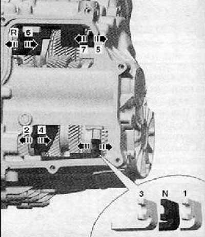
N - Idle position;
R - Reverse gear;
1 - first gear, 2 - second gear, 3 - third gear, 4 - fourth gear, 5 - fifth gear, 6 - sixth gear, 7 - seventh gear.
Note.
- If reverse is turned on, then the protruding pusher will jam behind the gearbox housing.
- Therefore, it is necessary to insert the mechatronics by hand into the extraction position.
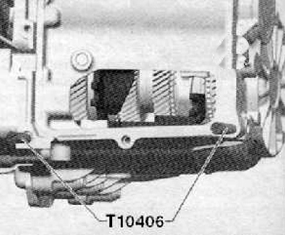
5. Screw in the guide pins by hand (Т10406), shown in the figure below.
Configuring the device to enable speed steps
Attention.
- Risk of damage to the mechatronics of the manual gearbox -J743-.
- When removing the pins, do not lean on the sensors.
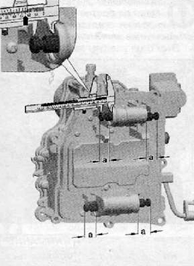
6. Adjust to the required position 4 devices for switching on the speed steps on the rear side of the mechatronics of the manual gearbox (J743).
Required position: -a- = 25 mm.
Note.
- Clean the sealing surface on the gearbox housing, to which the mechatronics will subsequently adhere.
- Residual oil on the sealing surface would subsequently lead to a diagnosis of a leak.
- The manual gearbox mechatronics seal -J743- must be secured all around.
7. Visually check the sensor. The clamp must not be damaged.
8. Install mechatronics. When grasping and installing, make sure that the shift forks are not accidentally squeezed out of their position. You should also be careful with respect to the setting lever and mechatronics pusher.
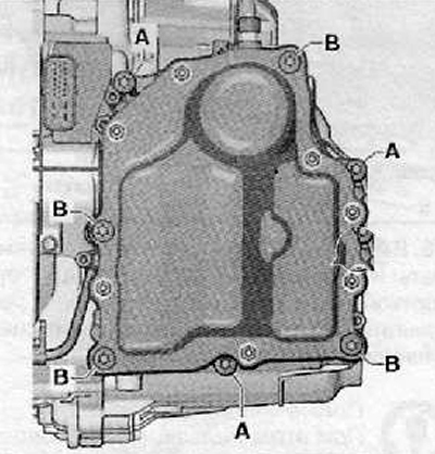
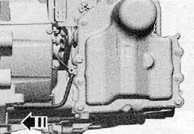
9. Screw in the screws crosswise by hand (A) (3 pieces, M8x35) And (IN) (2 pieces, M8x90), shown in the figure below.
10. Remove guide pins (Т10406).
11. Screw in the remaining screws by hand (IN) (2 pieces, M8x90).
12. Make sure that the pushers fit exactly into the inserts of the setting levers. The pushers should be pulled out by hand to such an extent that they fit into these liners.
13. Once again check the position of the pushers.
Note.
- Mistakenly adjacent pushrods damage the mechatronics.
- The pushers can be set in their correct positions with a hook bent from welding wire.
Note. Tighten all mechatronics screws for manual gearbox -J743- crosswise with the specified tightening torque.
14. Turning the mounting lever (Т10407) carefully and slowly to the right side, remove it.
Both clutch adjusters must properly fit into the recesses of the clutch levers.
In this case, the rubber cuffs of the clutch regulators must not be damaged.
The rubber cuffs must fit snugly against the mechatronics.
Incorrect assembly or damage to the rubber seals lead to oil leakage in the mechatronics.
15. Fit speed sender on gearbox input shaft -G182- in direction of arrow to gearbox housing as shown in figure below.
Note.
- Visually check the sensor. The clamp must not be damaged.
- The sensor must rest completely and securely with its tongue on the gearbox housing. If the sensor is not fixed, then this means that the clamp is broken off.
16. After removing the stopper from the air bleed tube, install the air bleed tube cover.
17. Install a cover over the adjusting levers against the ingress of contaminants. Tightening torque of fixing bolts: 8 Nm.
Attention. Do not touch the contacts in the gearbox connector with your hands, as electrostatic charge can destroy the control unit and thus the complete mechatronics module.
18. Touch the mass with your bare hand (corps), resulting in the discharge of an electrostatic charge.
19. Attach the mechatronics plug connector and secure it.
20. Re-install all holders and pipelines on the gearbox.
21. Install the engine cooling fan shroud.
22. Install the coolant hose at the bottom (1) on the radiator as shown in the figure below.
23. By connecting the plug connector (2), pour coolant.
24. Install the charge air hose.
25. Install the lower engine cover.
26. Fill with gear oil.
27. Check the adjusted position of the cable tightening of the preselector lever and, if necessary, adjust it.
28. Install the battery and battery holder.
29. Install the air filter.
30. Connect the battery.
Note. Using the special equipment, adapt the gearbox mechatronics module.