
Note.
- During assembly work, self-locking nuts and screws must be replaced.
- Replace screws that are tightened by an additional rotation to a certain angle, as well as O-rings and seals.
- Secure all hose connections with tube clamps in the original position.
- All cable clamps that were loosened or cut during removal must be reattached in their original position during reassembly.
- The selector lever cable tightening lock washer must always be replaced.
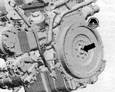
- Replace needle bearing -arrow- in crankshaft.
- Check whether dowel sleeves for centering the gearbox are present in the cylinder block: insert them if necessary.
- When installing the gearbox, make sure that the intermediate plate between the engine and gearbox is correctly installed.
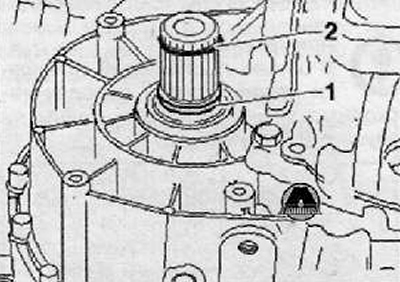
If a new gearbox is installed, the O-rings must be replaced (1) on splined shafts.
If a new gearbox is not installed, then the retaining rings should be replaced (2) on splined shafts.
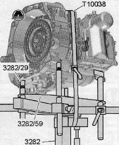
Raise gearbox carefully with engine and gearbox remover and installer -VAG 1383 A- and with gearbox support (3282) put in position for assembly.
Note.
- When lifting the gearbox, slide the selector lever cable tightening carefully into the counter support of the flexible rollers (Bowden cables)
- Do not bend or kink excessively the cable tightening of the selector lever.
- When lifting the transmission, be careful of all coolant lines and hoses.
The gearbox mounting tool -3282- must be adjusted with the spindles so that the engine and gearbox are well matched
The engine and gearbox must be brought close to each other by hand to such an extent that the engine flange touches the entire perimeter of the gearbox flange!
Screw the gearbox to the engine, while turning, if necessary, a little crankshaft.
2. Install the unit support as follows.
Insert gearbox bracket (1) into the space between the gearbox and the gearbox bearing bracket.
Screw the gearbox bracket (1) on the gearbox with new screws.
With the lead screw of the fixing suspension device -MP9-200 (10-222 A) - Raise the gearbox evenly to the gearbox bearing bracket.
screws (arrows) must be tightened by hand first.
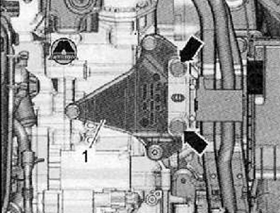
Attention. Before proceeding with screwing (arrows) Make sure that the gearbox bracket and the gearbox bearing bracket are parallel to each other, otherwise the threads may be damaged.
3. Remove gearbox mounting tool -3282- from gearbox.
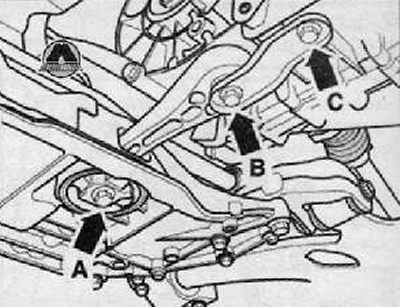
4. Install the rocker arm with new screws (arrows A, B and C), as shown in the figure below.
5. Install the drive shaft to the left and the drive shaft to the right.
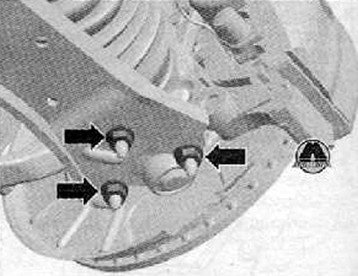
6. Screw the ball joint heads to the lower front suspension arms (arrows), as shown in the figure below.
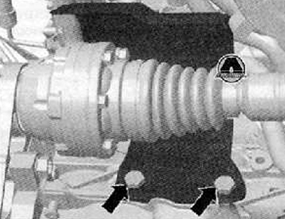
7. Screw the protective cap for the drive shaft to the right on the motor by tightening the screws (arrows) with the application of a torque of 35 Nm.
8. Install the charge air hose in the space between the charge air cooler at the bottom left and the charge air pipe.
9. Assemble the exhaust piping and the exhaust piping holder onto the axle suspension mounting beam without internal stresses.
10. Install starter.
11. Check the machine support.
12. Tighten, with the application of the prescribed tightening torque, the new gearbox bearing screws on the gearbox bracket.
13. Remove the fixing hanger MP9-200 (10-222 A).
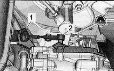
14. Move the cable tightening of the preselector lever (2) toward the shift shaft lever on the gearbox and secure with a new lock washer (1) in counterholder of flexible rollers (Bowden cables).
15. Install the battery and battery holder.
16. Check the adjusted position of the cable tightening of the preselector lever and adjust.
17. Install the air filter.
18. Install the liner (lining) wing from the niche of the left wheel.
19. Install the lower engine cover.
20. Install the front wheels.
21. If the vehicle level sender, front left -G78- has been removed, the headlight alignment must be monitored.