Note. Do not remove the key from the ignition switch.
2. Remove the top engine cover.
3. Remove the air filter.
4. Remove the battery and battery holder.
5. Remove the waterproof housing cover.
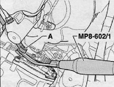
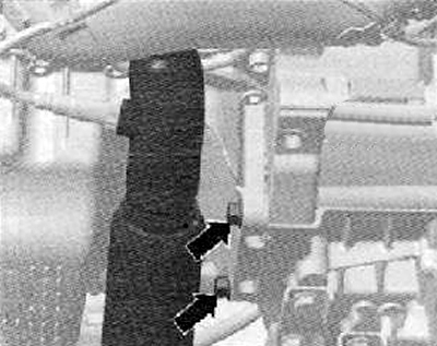
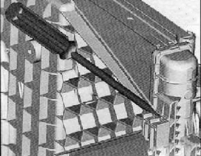
6. Using the inner panel removal tool (MP8-602/1), you should release the cable tightening of the preselector lever (A) from the shift lever as shown in the figure below.
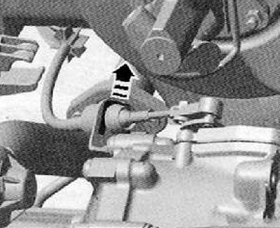
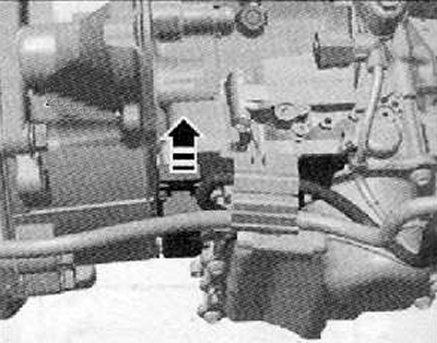
7. Removing the lock washer (arrow) selector lever cable, leave the selector lever cable in the assembly position.
Note.
- The lock washer -arrow- for the selector lever cable tightening must always be replaced.
- Do not bend or kink excessively the cable tightening of the selector lever.
- Do not press the cable tightening of the selector lever towards the rear out of the counterholder of the flexible rollers (Bowden cables). The cable tightening of the selector lever is removed from the counter support of the flexible rollers (Bowden cables) only during removal of the shift actuator.
8. Disconnect the ground wire (frame) from the mounting bolt of the gearbox bracket.
9. Remove plug connector and wire from starter.
10. Remove the starter assembly (see the relevant section in chapter Engine electrical equipment).
Note. Remove the second starter screw (it is not visible in the picture), remove the starter (2).
11. Unscrew all the upper bolts securing the gearbox to the engine. To do this, if necessary, use the key (Т10035).
Note.
- One of the bolts is in the starter hole (only for some types of engine, e.g. at 1, 4).
- This bolt must be removed.
Attention. Do not touch the contacts in the gearbox connector with your hands, as electrostatic charge can destroy the control unit and thus also the mechatronics module.
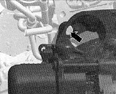
12. Unlock the lock of the mechatronics plug connector by pulling in the direction of the arrow and disconnect the plug connector as shown in the figure below.
13. Install the fixing suspension device (Т30099).
14. Use the lead screws to lightly prestress the (without lifting) engine-gearbox assembly.
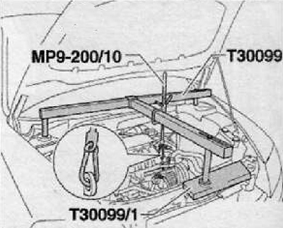
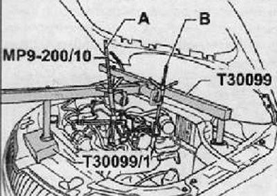
15. Install the fixing suspension device (Т30099) with special beam (Т30099/1), as shown in the figure below.
16. Using a lead screw, slightly prestress the (without lifting) engine-gearbox assembly (on the 1.2 l engine, only one outboard lead screw should be used).
17. Remove the front wheels.
Note. Once the drive shaft screw has been loosened, the vehicle must no longer be lowered to the ground.
18. Remove the lower engine cover.
19. Remove the front wheel arch liner (see relevant section in chapter Body).
20. Remove the charge air hose from the charge air cooler at the bottom left and from the charge air pipe.
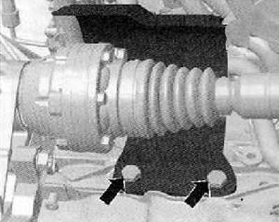
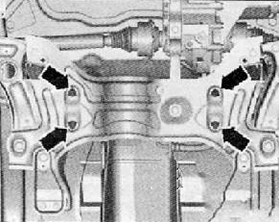
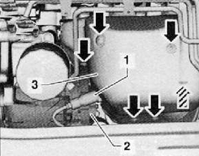
21. Remove the protective cover of the right drive shaft from the engine (arrows), as shown in the figure below.
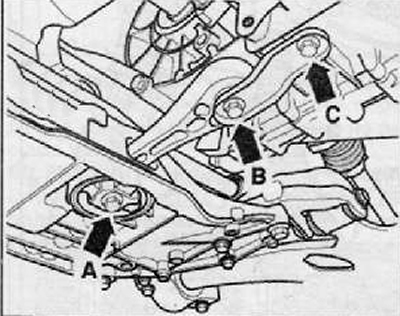
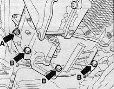
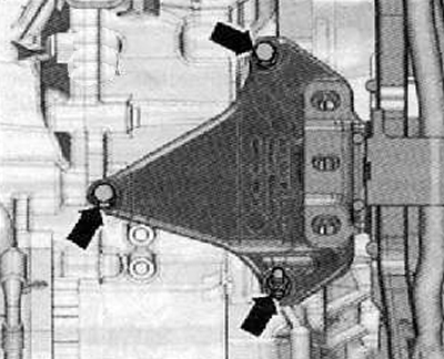
22. Remove the oscillating support by unscrewing the bolts (arrows A, B and C), as shown in the figure below.
23. Having separated the exhaust pipe at the place of the double fixing bracket, remove the exhaust pipe holder from the axle suspension mounting beam.
24. Tie the front of the exhaust pipe at the top.
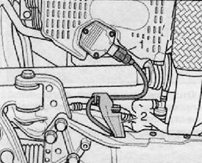
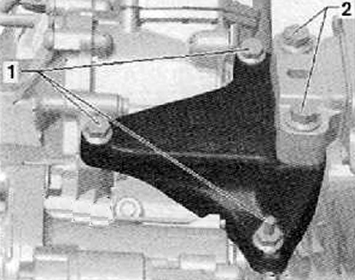
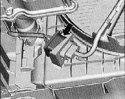
25. Disconnect plug connector (1) on the oil level and oil temperature sender -G266- as shown in the figure below.
26. Release the wiring harness from the holder (2), shown in the figure below.
27. Remove stabilizer holder from stabilizer.
28. Before proceeding with the extraction, it is necessary to fix the axle suspension mounting beam.
29. Remove suspension beam with bracket without steering gear housing, left suspension arm and stabilizer connecting rod.
Only for vehicles with splined shaft
30. Where fitted, remove vehicle level sender, front left -G78-.
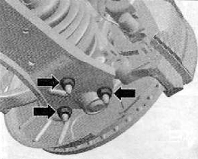
31. Loosen the fastening nuts (arrows) ball joint of the front suspension lower arm, as shown in the figure below.
32. Disconnect the ball joint from the front suspension lower arm assembly.
33. Press for example. with a wedge (Т10161) or mounting lever drive shaft to the left and right of the gearbox splined shafts.
34. Remove the left drive shaft.
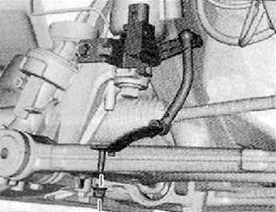
35. Unscrew the fastening bolts (arrows) steering gear to the front suspension subframe. Raise the steering box to the right and hang it from the ABS module mounting bracket.
36. Secure subframe assembly before removal.
37. Remove subframe assembly without steering gear.
38. Tie up the drive shaft as high as possible, as shown in the figure below. Do not damage the protective paintwork on the drive shaft.
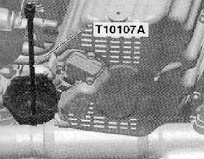
39. Remove the right flanged shaft using the special tool (TYU107A), as shown in the figure below.
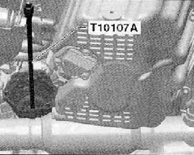 |  |
40. Using a suitable plug, plug the transmission outlet.
41. Unscrew the lower mounting bolts (arrows) and disconnect the front part of the outlet pipe of the exhaust system, as shown in the figure below (only for 1.4L engine).
42. Unscrew the lower connecting bolts (arrow A) And (arrow B) engine and gearbox as shown in the figure below.
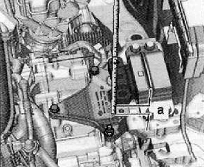
43. Loosen the fastening bolts by about one turn (1) gearbox mounting bracket as shown in the figure below. Unscrew the fixing bolts completely (2), shown in the figure below.
44. Then you should lower, using the lead screw of the fixing suspension device (MP9-200) (10222 A) engine and gearbox to such an extent that a gap of dimension -a- is formed between the gearbox bracket and the gearbox bearing.
Size -a- = 60... 70 mm.
45. Remove the bolts securing the transmission mounting bracket assembly (arrows), as shown in the figure below.
46. Disconnect the wiring harness connector, shown by the arrow in the figure below.
47. Using a suitable tool, unfasten and remove the engine cooling fan shroud as shown in the figure below.
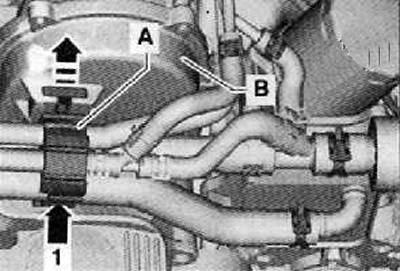
48. Open bracket (A) and disconnect the water hoses of the cooling system from the bracket. Do not disconnect hoses from fittings.
49. Detach the bracket at the bottom (arrow 1) and disconnect from the timing belt cover (IN), move in the direction of the arrow as shown in the figure below.
50. Remove lambda sensor -G39- (1), shown in the figure below.
51. Disconnect the wiring harness connector (2) from the generator and remove the thermal insulation cover (3) with exhaust manifold with turbocharger (arrow), as shown in the figure below.
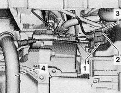
52. Disconnect wiring harness connectors (1...3) from the bottom mounting bracket on the front of the gearbox.
53. Disconnect the front exhaust pipe with catalytic converter (4), as shown in the figure below.
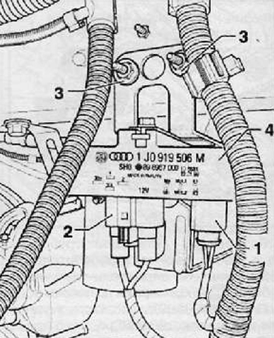
54. Loosen the fastening nuts (3) on the left side of the rail and remove the engine cooling fan control module (4), shown in the figure below
Note. Do not disconnect wiring harness connectors (1) And (2).
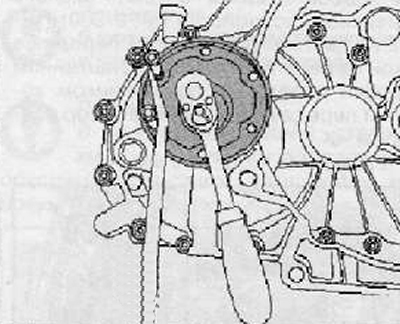
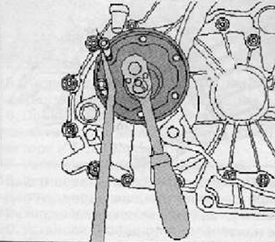
55. Remove the right flanged shaft using the special tool shown in the figure below.
56. To remove, screw two screws into the holes in the flange. Then, blocking the flange from rotation with a crowbar, remove it from the gearbox, as shown in the figure below.
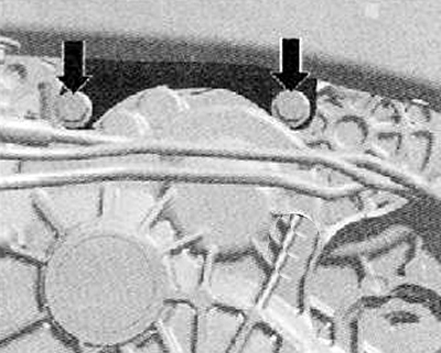
57. Plug the outlet in the gearbox.
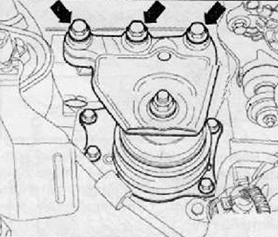
58. Remove the bolts securing the engine support mounting bracket assembly (arrows), as shown in the figure below.
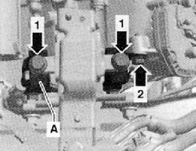
59. Unscrew the mounting bolts (arrow 1) gearbox mounting support on console (A), as shown in the figure below.
60. Unscrew the rear mounting bolt (arrow 2) consoles (A) on the gearbox as shown in the figure below.
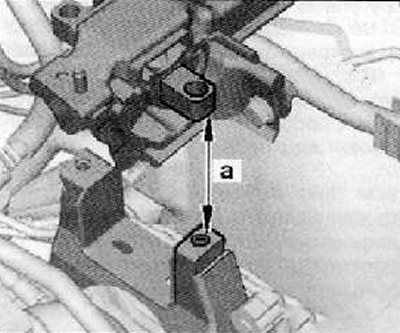
61. Lower the gearbox assembly with the engine to a distance a. a = 85 mm.
62. Gently lower the engine assembly.
63. Unscrew the fastening bolts (arrows) transmission console, starting from the left wheel arch, as shown in the figure below.
64. Remove the console from the gearbox.
Note. Gear box attachment (3282) for removing the gearbox OAM is adjusted using the setting plate (3282/59) and is installed on the device for removing and installing the engine and gearbox VAG 1383 A.
65. Adjust the position of the shoulders of the gearbox mount on the holes in the mounting plate (3282/59).
66. Screw the fixture fasteners according to the marks on the mounting plate (3282/59).
67. Place engine and gearbox remover and installer -VA G 1383 A- under the vehicle. Arrow on setting plate (3282/59) points in the direction of the vehicle.
68. Align the gearbox mount (3282) parallel to the gearbox.
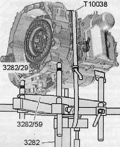
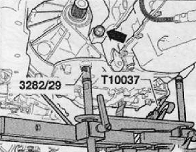
69. Screw fingers (3282/29) into the gearbox.
70. Both remaining fasteners should be installed on the gearbox according to the drawing. In this case, the metal sheet of the mandrel should be placed under the gearbox housing, and not under the mechatronics.
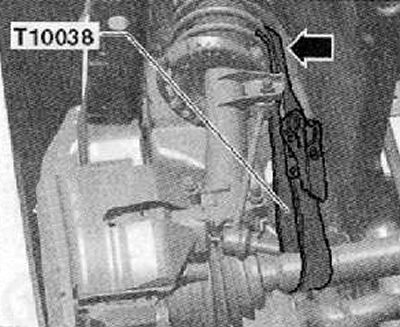
71. The gearbox should be fixed with a clamp (Т10038).
72. Support gearbox from below by lifting engine and gearbox remover and installer -VAG 1383 A-.
73. Unscrew the last connecting bolt (arrow B) engine and gearbox as shown in the figure below.
74. Press the gearbox from the centering bushings.
75. Separating the gearbox carefully from the engine, carefully lower it.
76. When lowering the gearbox, remove the cable tightening of the selector lever from the counter support of the flexible rollers (Bowden cables).
Note.
- When lowering the transmission, be careful of all coolant lines and hoses.
- Do not bend or kink excessively the cable tightening of the selector lever.
Note. In some cases, the holders are forward on the gearbox.
Note. If a new gearbox is to be installed, the brackets must be installed on the new gearbox.