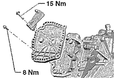
Note: Follow the instructions for the DSG "0CW" automatic transmission. The clutch automatically adjusts the working clearance. Fluctuations may adversely affect the clutch adjustment device. Even if the mechatronics is removed, abruptly pulling out the "T10407" crowbar under the engagement levers may adversely affect the adjustment device. Ensure sufficient distance to the gearbox for removing the mechatronics. On some vehicles, it is necessary to dismantle components that are not directly connected to the mechatronics, e.g. the bracket on the mechatronics cover screws. Additional work must be performed when disconnecting and connecting the battery ground wire.
The mechatronics remains filled with oil
Set the control lever to the "P" position. Immediately before removing the mechatronics, perform the basic setting of the "neutral position" of the gearbox. Turn on the ignition. Set the -Guided functions- mode, then select "02 7-speed DSG gearbox" and then "basic setting of the idle mode". Turn off the ignition. Disconnect the battery ground wire with the ignition off. Remove the air filter. Remove the battery and battery bracket.
Caution! Risk of damage to gearbox components. It is strictly forbidden to touch the gearbox connector contacts with your hands. A static discharge can damage the control unit and, along with it, the Mechatronic unit.
Touch with your hand (without gloves) to ground to remove any electrostatic charge. Unlock the mechatronics connector by pulling in the "direction of the arrow" and disconnect the connector.
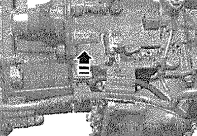
Remove the vent cap and plug it with a suitable plug to prevent oil from leaking out.
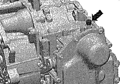
Note: If the mechatronics breather is damaged during removal, it must be replaced. Seal the ventilation hole with a clean plug from the plug kit for the engine "MS 6122" or with the cap "OAM 325120 A".
Remove the lower engine noise insulation casing. Disconnect the charge air hose from the left lower charge air cooler and the charge air pipe. Disconnect the connector "1" of the radiator fan. Disconnect the clamps "arrow B" and remove the fan casing.
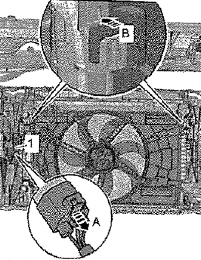
Note: The fan shroud can accommodate two fans.
Remove the electrical wires from the front mechatronics holder and tie them up. Disconnect the holder from the mechatronics cover. Place a pan under the gearbox to collect the oil. Unscrew the threaded plug of the oil drain hole "see arrow" on the gearbox.
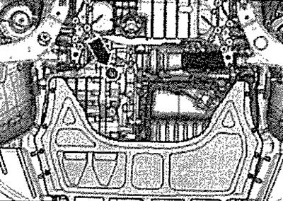
Allow the oil to drain. Install the oil drain plug.
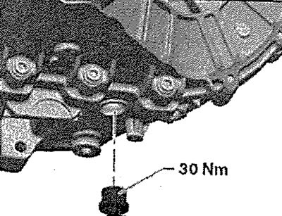
Note: After removing the mechatronic unit, pump out any remaining oil in the gearbox using a device for bleeding air from the fuel system of a diesel engine, e.g. "VAS 5226".
Remove the dirt protection cover over the dual clutch engagement levers, if present.
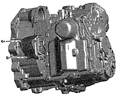
Remove the electrical wires from the front lower mechatronics holder and tie them up. Disconnect all holders from the gearbox.
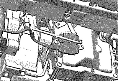
Using a screwdriver, carefully unlock the gearbox input speed sensor "G182" M and remove it from the housing in the "direction of the arrow".
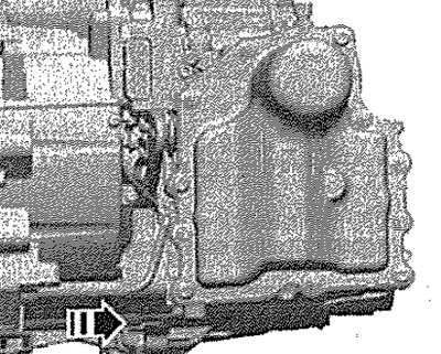
Note: The next step is to remove both dual clutch release levers from the pushrods. Otherwise, the levers will sit on the mechatronics pushrods and cannot be removed.
Insert the "T10407" crowbar under the pushers "2" between the gearbox housing and both release levers "1" "arrow", as shown in the figure.
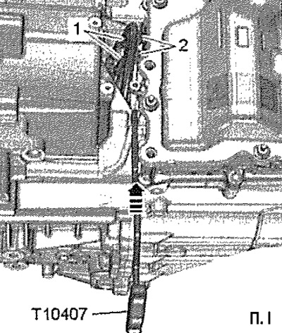
Push the "T10407" mount only so far that the groove and the recess on the gearbox housing are in the same plane of the "arrow", as shown in the figure. Do not insert it all the way.
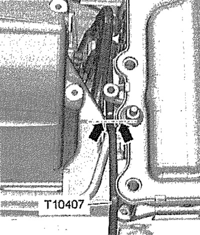
Note. The grooves on the body and the groove on the lever must be at the same level. Do not insert the "T10407" mount all the way. The back side of the mount must be adjacent to the gearbox body.
When turning, do not apply significant force to the end of the lever. This will prevent the mount from falling out when turning.
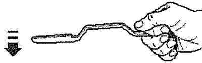
Turn the T10407 crowbar in the direction of the arrow to the left and remove the engagement lever from the pusher.
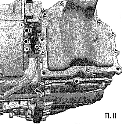
Note. Do not remove the "T10407" mounting tool. The mounting tool remains between the dual clutch engagement levers and the gearbox housing during the entire assembly period. Removing the mounting tool may damage the automatic dual clutch adjustment device.
If necessary, press the T10407 mount with a screwdriver against the gearbox and push both dual clutch engagement levers out of the Mechatronic unit.
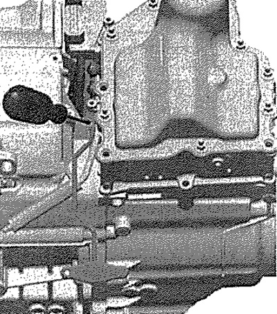
Note: Do not damage the rubber bushings of the dual clutch regulator. Risk of damage to the mechatronics of the DSG gearbox "J743". Do not loosen the screws of the mechatronics cover for the dual clutch gearbox "J743". Place the removed mechatronics of the DSG gearbox "J743" so that no oil flows out through the ventilation holes of the mechatronics. If oil flows out, it is not possible to top up the oil level and the mechatronics must be replaced!
Remove the long screws "B" (4 pcs., M8 x 90) in a crosswise order. Remove the remaining screws "A" (3 pcs., M8 x 35) in a crosswise order.
Note: Do not remove more than 7 screws! "These are 4 long and 3 short screws". Do not loosen the screws of the mechatronics cover for the dual-clutch transmission. The mechatronics for the dual-clutch transmission "J743" may only be touched or handled after the electrostatic charge has been discharged via a grounded object, such as the main contact to ground. Never touch the plug-in contacts in the gearbox connector with your hands, so that the static discharge does not damage the ECU and mechatronics.
Touch with your hand (without gloves) to ground to remove electrostatic charge. Remove mechatronics.
Caution! Risk of damage to the mechatronics KHDSG "J743". It may happen that the mechatronics cannot be removed. In this case, the gear selector clamps the mechatronics in the upper left area. The mechatronics cannot be removed by additional force. In this case, the mechatronics must first be brought into the position for removal manually. The "removed" mechatronics is returned filled with oil (plug the vent with a suitable plug).
Install mechatronics with the gearbox installed.
Manually move the mechatronic unit for the dual-clutch transmission "J743" to the "release position"
It may happen that the mechatronics cannot be removed. In this case, the actuator is "clamped" "at the top left" on the gearbox housing "see arrow".
Data Copied from the portal [www.skodabook.ru]
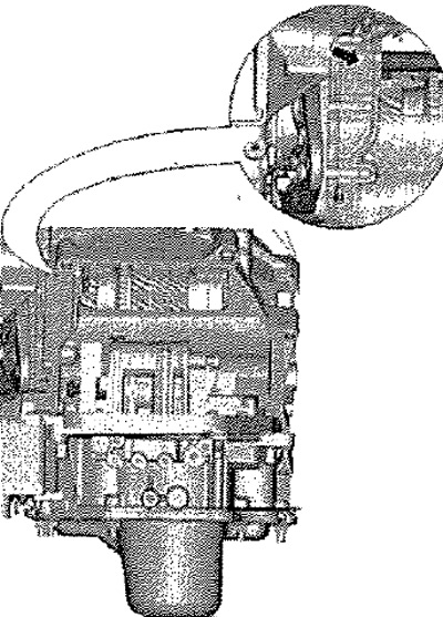
Only in the case where the "release position" cannot be set using the "VAS/ODIS" vehicle tester, it is necessary to bring the Mechatronic unit to the "release position" manually. The "clamped" actuator can now be pushed back by hand to the "release position". To do this, remove the gearbox lock cover when parking.
Caution! If dropped, the mechatronics may fail! After being brought into the "removal position" manually, the mechatronics is not secured and may fall out of the gearbox. Until this happens, secure the mechatronics to the gearbox from falling out with at least one screw.
Fully insert the mechatronics into the gearbox and secure with one screw. Set the control lever to position "P", Remove cover "1" of the parking lock mechanism.
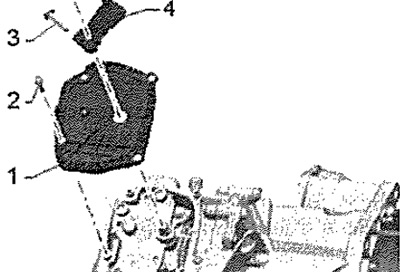
Note: Before the next work step, the Mechatronic unit must be secured against falling out of the gearbox with at least one screw.
Press the gear shift fork through the hole in the direction of the arrow.
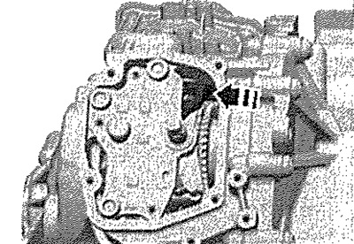
Thus, the "clamped" actuator is pressed out, and the mechatronic can be removed. Remove the Mechatronic unit. Clean the sealing surfaces on the gearbox and on the gearbox lock cover when parking.
Note: After finishing work with the mechatronics and after its installation, fill the gearbox with oil through the hole in the parking lock. Lubricate the sealing ring in the cover with sealing grease "G 052128 A1". Replace the gearshift lever mounting screws.
Install the parking lock cover and gear shift lever.