
Removing
1. Disconnect the negative terminal from the battery.
2. Set the gear selector to the position «R».
3. Remove the top decorative engine cover.
4. Remove the air filter housing assembly (see the relevant section in chapter Intake and exhaust system).
5. Remove the intake duct (see the relevant section in chapter Intake and exhaust system).
6. Disconnect the wiring harness connector from the electronic transmission control unit.
7. Remove the battery together with the base plate.
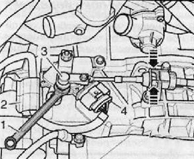
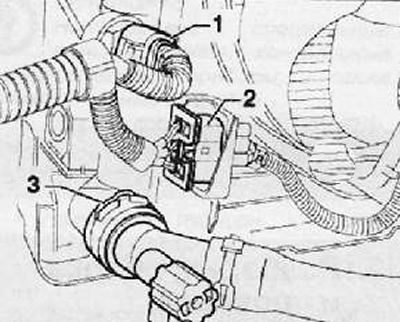
8. Using an open end wrench (1), disconnect the transmission control cable (3) from the actuating lever, as shown in the figure below.
9. Compress the latches on both sides (arrows) and disconnect the transmission shift cable from the mounting bracket on the gearbox housing as shown in the figure below.
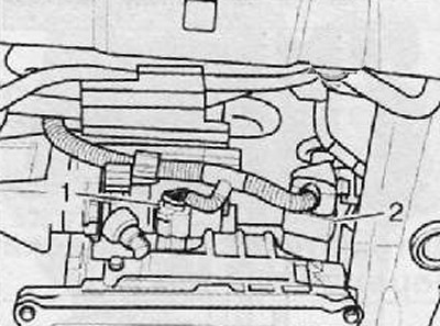
10. Disconnect the wiring harness connector (4) and release the cable from the bracket (2), as shown in the figure below.
11. Remove the transmission control cable mounting bracket from the transmission case.
12. Unscrew the mounting bolt and disconnect the wire «masses» (3), shown in the figure below.
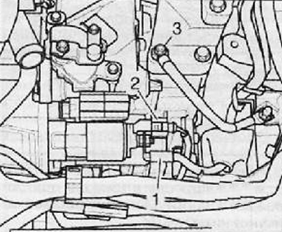
13. Disconnect wiring harness connectors (1) And (2) from the starter and release them from the retainers.
14. Mark the transmission fluid coolant hoses to prevent misconnection.
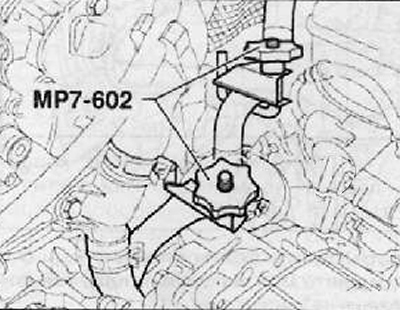
15. Using a special tool (MP7-602). pinch the transmission fluid coolant hoses as shown in the figure below. Disconnect the transmission oil cooler hoses.
16. Plug the outlet holes of the radiator of the transmission fluid cooling system with special plugs.
17. Unscrew all the upper bolts securing the gearbox to the engine.
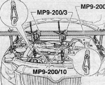
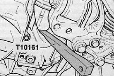
18. Install a special device for hanging the power unit on the car (MP9-200), as shown in the figure below.
19. Fix the power unit assembly on the tool spindles.
Note. The picture below shows the vehicle schematically and may differ from the actual one.
20. Unscrew the fastening bolts (1) And (2), then remove the transmission console assembly (A), as shown in the figure below.
21. Remove both front wheels.
22. Remove the soundproofing cover.
23. Remove the front left wheel arch liner.
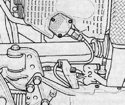
24. Disconnect the wiring harness connector (1) from the engine oil level and temperature sensor, as shown in the figure below.
25. Disconnect and remove the engine oil level and temperature sensor wiring harness mounting bracket (2), as shown in the figure below.
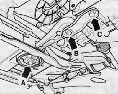
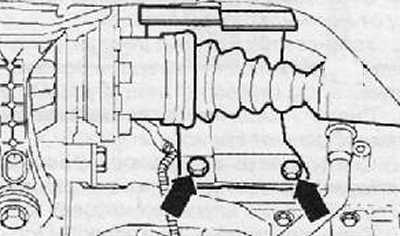
26. Unscrew the fastening bolts (A, B and C) and remove the pendulum support as shown in the figure below.
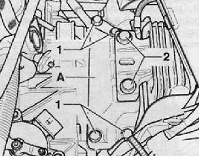
27. Disconnect wiring harness connectors (1) And (2) automatic transmission as shown in the figure below.
28. Remove the wiring harness mounting bracket from the bottom of the starter.
29. Take the mounting bracket along with the wires towards the front of the engine compartment.
30. Remove starter assembly (see the relevant section in chapter Engine electrical equipment).
31. Unscrew the mounting bolts and remove the protective cover of the drive shaft, as shown in the figure below.
32. Disconnect the front section of the exhaust pipe of the car's exhaust system.
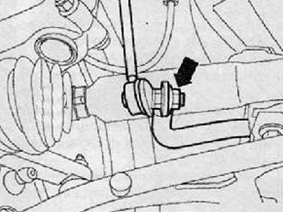
33. Unscrew the fastening nut (arrow) anti-roll bars to the stabilizer bar as shown in the figure below. Carry out this operation on both sides of the anti-roll bar.
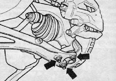
34. Unscrew the nuts securing the lower suspension arm to the ball joint, as shown in the figure below.
35. To turn away nuts of fastening of a rack of the gauge of height of the car from the left side of the car.
36. Disconnect the lower front suspension arm from the steering knuckle.
37. Move aside the shock absorber strut to remove the outer constant velocity joint from the front wheel hub.
38. Suspend the drive shaft using a suitable piece of wire and rope.
39. Repeat the above operations on the opposite side of the vehicle.
40. Remove the cover of the service hole for access to the torque converter fastening nuts.
41. Unscrew the six fastening nuts (arrows) torque converter as shown in the figure below. To do this, turn the torque converter every time by 60 degrees.
Note. If not all six fastening nuts are removed, the torque converter may fall out of the gearbox housing.
42. Lower the power unit using special equipment by 50 mm.
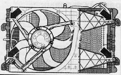
43. Disconnect the wiring harness connector (2), shown in the figure below.
Note. Disconnect the A/C hose mounting bracket from the cooling fan shroud.
44. Unscrew the mounting bolts (arrows) and remove the shroud assembly with cooling fans as shown in the figure below, downwards.
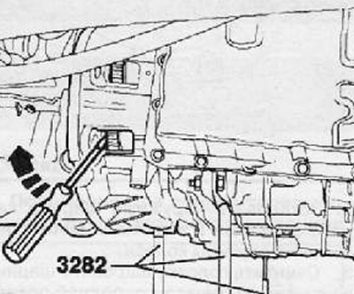
45. Install a special support (3282) on the gearbox housing assembly using a special hydraulic jack VAG 1383A.
46. Install the adjusting plate (3282/36) on the gearbox housing (Adjustment plate can only be set in one position).
47. Align the gearbox support arms with the holes in the adjusting plate.
48. Fix the mounting elements with bolts, as shown in the figure below.
49. Place a special hydraulic jack under the car, adjusting its location according to the arrows on the adjusting plate.
50. Install the adjusting plate parallel to the gearbox housing.
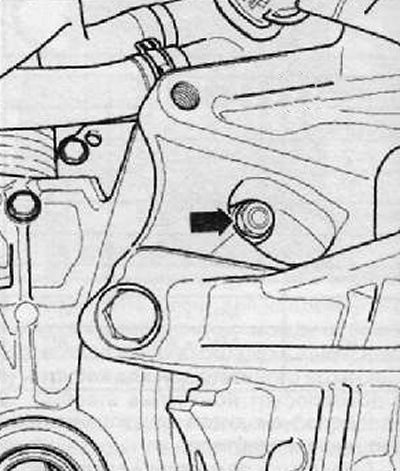
51. Fix the gearbox on the support using the mounting bolt (1), as shown in the figure below.
52. Support the gearbox by lifting the automatic transmission support.
53. Unscrew the remaining bolts securing the gearbox to the engine.
54. Disconnect the transmission from the engine while working on the torque converter to disengage it from the drive plate.
55. Press the torque converter again against the transmission fluid pump, as shown by the arrow in the figure.
56. Gently shift the gearbox towards the subframe.
57. Carefully lower the hydraulic jack together with the transmission assembly.
58. Change the location of the gearbox on the spindles of the automatic transmission supports (3282), when it is lowered.
59. Secure the torque converter from falling out of the gearbox housing.
Installation
1. Installation is made in reverse order to removal.