
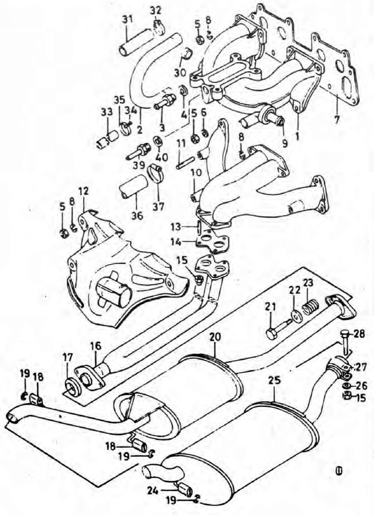
Pic. 4.9. Intake and exhaust manifolds, exhaust system components
1. Intake manifold; 2. Coolant hose; 3. Vacuum hose connection; 4. O-ring; 5. Nut; 6. Washer; 7. Gasket (common to both collectors); 8. Washer; 9. Hose connection; 10. Exhaust manifold; 11. Bolt; 12. Air heating casing; 13. Bolt; 14. Gasket; 15. Locknut; 16. Outlet exhaust pipe; 17. O-ring; 18. Flexible rubber suspension; 19. Retaining ring; 20. The central part of the exhaust system; 21. Bolt; 22. Mounting plate; 23. Spring; 24. Flexible rubber suspension; 25. Rear exhaust system; 26. Washer; 27. Bracket; 28. Bolt; 30. Cork; 31. Insulating tube; 32. Bracket; 33. Hose; 34. Bracket; 35. Screed; 36. Air heater supply hose; 37. Bracket; 39. Vacuum hose connector; 40. O-ring.
Note: Please refer to the warning in the Chapter 1.
Removing
1. While the intake manifold can be removed with the carburetor attached to it, it is still recommended to remove the carburetor first to improve access to the manifold fasteners (Chapter 11).
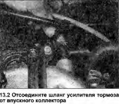
2. Disconnect the brake booster vacuum hose from the intake manifold (see illustration).
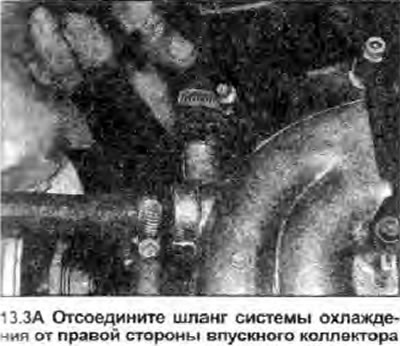
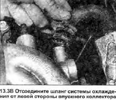
3. (Engine must be cold), loosen the expansion tank filler cap. Pinch the coolant hoses near the manifold connections, then loosen the mounting brackets and disconnect the hoses from the manifold (see illustrations).
 |  |
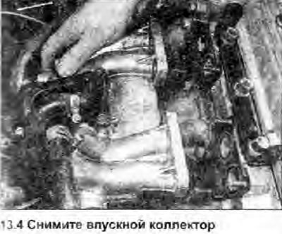
4. Remove the six mounting nuts, remove the flat washers and remove the manifold from the studs. Do not damage the gasket (see illustration).
5. If the gasket is damaged or in poor condition, replace it.
Installation
6. Install in reverse order. Make sure the contact surfaces of the manifold and cylinder head are clean and in good condition. Fasten all hoses securely and check connections for leaks. Check the coolant level and, if necessary, top up as described in Section 1.