



Contents: Outer CV joint ⬇ Inner CV joint ⬇
1. Remove the drive shaft (see section Removal and installation drive shafts) and the corresponding CV joint.
Outer CV joint
2. Clamp the drive shaft in a vice with soft jaws and release the bands securing the outer CV joint protective boot.
Note: If necessary, the bandage tapes can be simply cut off.
3. Unscrew the cover so that the hinge is accessible. Remove excess grease.
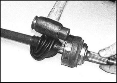
4. Knock the joint off the shaft with sharp blows of a hammer through a drift. The joint is secured to the shaft with a retaining ring. When knocking the assembly off in the manner described, the ring falls into a specially provided groove on the shaft, which allows the CV joint to be removed without hindrance.
5. After removing the joint, remove the retaining ring from its groove and discard it - the ring must be replaced during assembly.
6. Remove the rubber protective cover of the CV joint from the shaft.
7. Thoroughly wash the removed joint with kerosene or other suitable solvent. Visually inspect the condition of the internal components of the assembly.
8. While moving the inner part of the joint, inspect each of the balls in their upper position. Pay attention to cracks, flattening and cavities.
9. Check the guides in the inner and outer races of the assembly for developed areas where the tightness of the ball fit is violated. At the same time, check the condition of the separator - the presence of cracks between the windows is unacceptable.
10. A worn or damaged joint must be replaced. If the CV joint is deemed fit for further use, prepare a new protective boot, banding tapes, a retaining ring and grease for packing the CV joint (see Specifications).
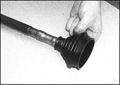
11. Wrap the journal splines with tape and carefully put the new CV joint protective cover on the shaft. Try not to allow the plastic bushings installed in its inner jaws to shift while putting the cover on.
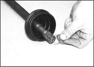
12. Remove the tape and place a new retaining ring on the shaft. Make sure the ring is seated correctly in the groove on the shaft.
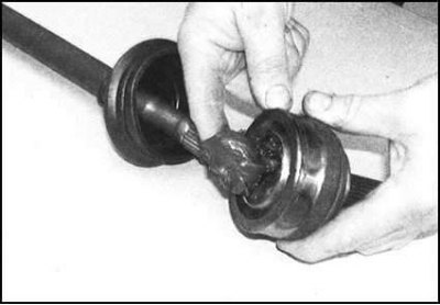
13. Fill the joint with fresh grease. Fill the remaining grease in the package into the boot.
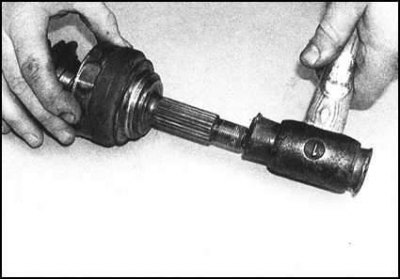
14. Place the CV joint on the shaft journal and place its edge on top of the retaining ring. Using sharp blows of a soft-faced hammer on the outer part of the joint, seat the latter on the shaft. Tug the assembly to ensure that it is securely fixed on the shaft with the retaining ring.
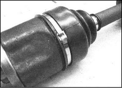
15. Place the outer lips of the boot in the groove on the CV joint assembly, secure the inner lips to the shaft flange. Lift the inner edge of the boot to release the air from underneath it.
16. Make sure the cover fits correctly, then secure it with bandage tapes.
Note: There are two types of bandage tapes available.
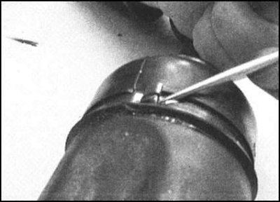
17. Most often, bandage tapes are used to secure the protective covers of the CV joints; they are simply wrapped around the cover and fixed by squeezing the protruding sections. In the absence of a special tool, the bandage clamps can be squeezed using pliers or side cutters (be extremely careful not to accidentally cut through the tape).
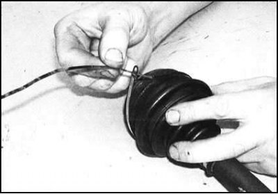
18. Less common are bandage tapes in the form of metal strips equipped with a buckle clamp at one end. After wrapping around the cover, the free end of the tape is passed through a groove in the buckle. Having correctly positioned the tape on the cover, arm yourself with a special hook made from a welding electrode and pliers. Having tightly pulled the tape around the cover, bend its free end back and throw it over the buckle. Use side cutters to cut off the excess tape behind the buckle, then press the remaining "tail" firmly down.
19. Make sure the boot is securely fastened, then check that the joint rotates freely in all directions. The shaft can now be installed on the vehicle (see section Removal and installation drive shafts).
Inner CV joint
1. Clamp the shaft in a vice with soft jaws and release the bands securing the inner CV joint protective cover.
Note: The tapes can be cut if necessary.
2. Fold the boot back to expose the hinge. Remove any excess grease, then use paint or a marker to mark the position of the hinge housing relative to the shaft.
3. Remove the end shell from the hinge housing and remove the housing from the shaft. Try to prevent the rollers from falling out of the tripod assembly - wipe the latter and wrap it with tape from the outside.
Note: It is extremely important to install all internal components of the joint strictly in the previous order, so care must be taken to maintain the installation position of the tripod assembly during the removal of the housing. Violation of this requirement may lead to a significant reduction in the service life of the CV joint.
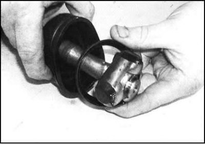
4. Remove the outer casing shell from the shaft by throwing it over the tripod assembly. Try to remember the installation position of the shell.
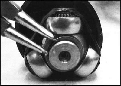
5. Mark the position of the tripod assembly relative to the shaft. Remove the retaining ring and pull the assembly off the shaft journal. If the tripod assembly is too tight on the shaft, use a 2-legged puller to remove it. The jaws of the puller legs are inserted under the inside of the assembly - do not allow the blades to come into contact with the rollers. Alternatively, support the inside of the assembly and press the shaft out of it using a hydraulic press - do not apply load to the rollers under any circumstances.
6. After removing the tripod assembly from the shaft, the protective cover of the joint can be removed.
7. Thoroughly wash the joint components with kerosene or other suitable solvent - try not to wash off the mounting marks. Perform a thorough inspection of the joint.
8. Check the crosspiece and tripod assembly rollers for signs of wear. Inspect the outer casing and its end shell. Assess the freedom of rotation of the rollers. If any defects are detected, replace the joint. If the CV joint is deemed fit for further use, prepare new banding tapes, a protective cover, a retaining ring and the required amount of grease of the required grade (see Specifications).
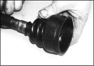
9. Wrap the splines of the shaft journal with tape. Carefully place the protective cover of the CV joint on the shaft, placing it in the receiving groove.
10. Remove the tape and place the outer casing of the hinge on the shaft (make sure the shell is turned in the correct direction).
11. While aligning the landing marks applied during dismantling, place the tripod assembly on the splines of the shaft journal. Carefully tap the assembly into its regular place (use a hammer and a soft metal punch). Be careful not to damage the splines of the shaft and the hinge rollers.
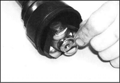
12. Secure the tripod assembly to the shaft using a new retaining ring. Make sure the ring is seated correctly in its groove.
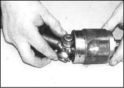
13. Remove the tape wrapped around the rollers, then put on the outer hinge housing.
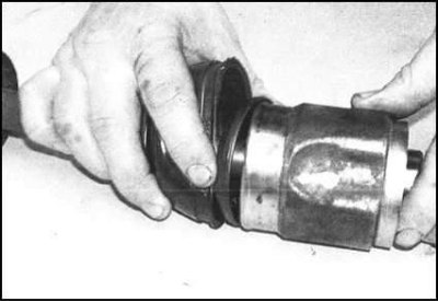
14. Make sure that the mounting marks applied during dismantling are aligned. After making sure that the components are installed correctly, secure the housing with the shell.
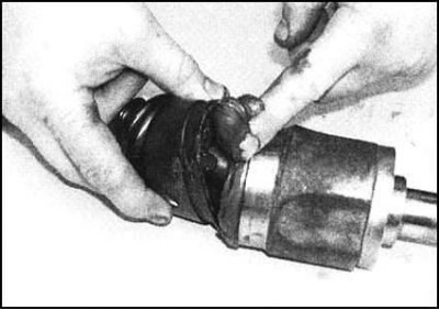
15. Evenly fill the cavities of the tripod assembly and the outer housing of the hinge with grease. Fill the remaining grease into the boot.
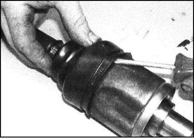
16. Insert the outer lips of the protective cover into the groove on the outer housing of the hinge, then carefully lift the edge, releasing air.
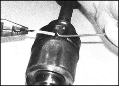
17. In accordance with the instructions given in paragraphs 17 and 18 of the Outer CV Joint subsection, secure the boot with two bandage straps.
 |
 |
18. Check the freedom of rotation of the CV joint in all directions, then install the drive shaft in its standard place on the vehicle (see section Removal and installation drive shafts).