



Contents: Removal ⬇ Installation ⬇
Removal
Note: A new hub nut and a replacement lower control arm ball joint tie rod nut will be required for assembly.
1. Remove the wheel/hub cap, then loosen the hub nut and wheel nuts.
2. Support the rear wheels with chocks, set the parking brake, then jack up the front of the car and place it on supports. Remove the corresponding front wheel.
3. Drain the transmission oil. After replacing the sealing washer, screw the drain plug of the manual transmission case back into its regular place and tighten it with the required force.
4. On ABS equipped models, remove the wheel sensor from the hub assembly (see Chapter Brake system).
5. Remove the cotter pin, loosen the tie rod ball joint nut and release the joint from the hub assembly pivot arm (see Chapter Suspension and steering).
6. Loosen the hub nut and remove the washer.
Note: If you are unable to loosen the hub nut before raising the vehicle off the ground, replace and tighten the pair of wheel bolts securely. Have an assistant firmly apply the foot brake to prevent the hub from turning, then loosen and remove the hub bolt. The removed hub nut cannot be reused and must be replaced during assembly.
7. On models equipped with a front anti-roll bar, loosen the nut securing the stabilizer bar strut to the lower control arm. Remove the washer and take out the lower rubber support cushion.
8. On all models, loosen the nut of the ball joint clamp bolt securing the lower control arm to the hub assembly. Using a pry bar, turn the arm, releasing the joint from the hub assembly. On models equipped with an anti-roll bar, try not to drop the upper rubber pad and the washer of the rod mount. The clamp bolt and its nut must be replaced during assembly.
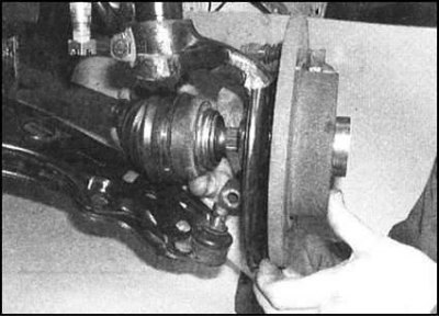
9. Carefully pull the hub assembly outward, removing it from the splines of the outer CV joint of the drive shaft. If necessary, the shaft can be knocked out of the hub using a soft-faced hammer. Immediately tie the released shaft with wire to the suspension elements to avoid damaging the inner joint and its protective cover.
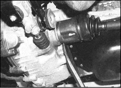
10. Being careful not to damage the crankcase, carefully pry up the inner CV joint with a pry bar or large screwdriver and release the inner shaft journal from the differential assembly.
11. Remove the shaft from under the vehicle (try not to damage the differential seal).
Note: Never lower the vehicle to the ground after removing one or both drive shafts. This practice can cause damage to the wheel bearings. If you need to move the vehicle, temporarily insert the outer end of the shaft into the hub of your wheel and secure it with a nut, then tie the inner end to the suspension components with wire.
If it is necessary to remove both drive shafts, you should take care to secure one of the side gears in the differential box. After removing the first shaft, insert a suitable diameter into the hole in the crankcase (about 26 mm) rod, passing it through the hole in the gear. Leave the other end of the rod protruding freely from the box. If one or more gears fall inside the assembly, you will have to disassemble the gearbox to remove them.
Installation
1. Before installing the drive shaft, check the condition of the sealing gland of its seat in the differential housing. If necessary, replace the seal (see section Replacing oil seals).
(Original text is located on: SkodaBook)
Note: The authors of this Manual recommend replacing the seals regardless of their condition.
2. Using a small screwdriver, remove the CV joint retaining ring from the end of the inner shaft journal and install a new one in its place. Make sure the ring is seated correctly in the groove.
3. Carefully wipe the splined portion of the journal and the surface of the walls of the hole in the differential housing. Lubricate the sealing lips of the oil seal, splines and shaft shoulders with a thin layer of thick grease. Make sure that the rubber protective cover of the CV joint is securely fixed with bandages.
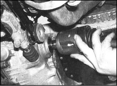
4. Being careful not to damage the seal, engage the shaft with the splines of the differential side gear hub in the gearbox. Push the shaft into the gearbox until it stops and make sure it is securely fixed with the retaining ring. If necessary, use a soft-faced hammer to seat the shaft.
5. Align the outer CV joint and push its journal into the hub assembly. Install the washer and thread the hub nut on, tightening it only by hand for now.
6. Use the lever to push the lower control arm assembly down, insert the ball joint into its regular place, then release the lever. Make sure that the ball joint pin of the support is fully inserted into its socket in the hub assembly clamp. Insert the tie bolt, screw the nut onto it and tighten it to the required force. On models equipped with an anti-roll bar, install the stabilizer bar strut onto the lower control arm assembly, making sure that the upper rubber cushion and washer are seated correctly.
7. Where required, reinstall the lower rubber cushion and anti-roll bar strut washer, screw on the nut and tighten it to the required torque.
8. Insert the steering rod end into the hub assembly pivot arm and secure it with its nut, tightening the latter securely. Secure the nut with a new cotter pin.
9. On models equipped with ABS, install the wheel sensor on the hub (see Chapter Brake system).
10. Replace the wheel, lower the vehicle to the ground and tighten the wheel bolts to the required torque.
11. Tighten the hub nut to the required torque, then install the wheel/hub cap.
12 Fill the gearbox with the required amount of transmission oil of the required grade.