



Drive shaft design
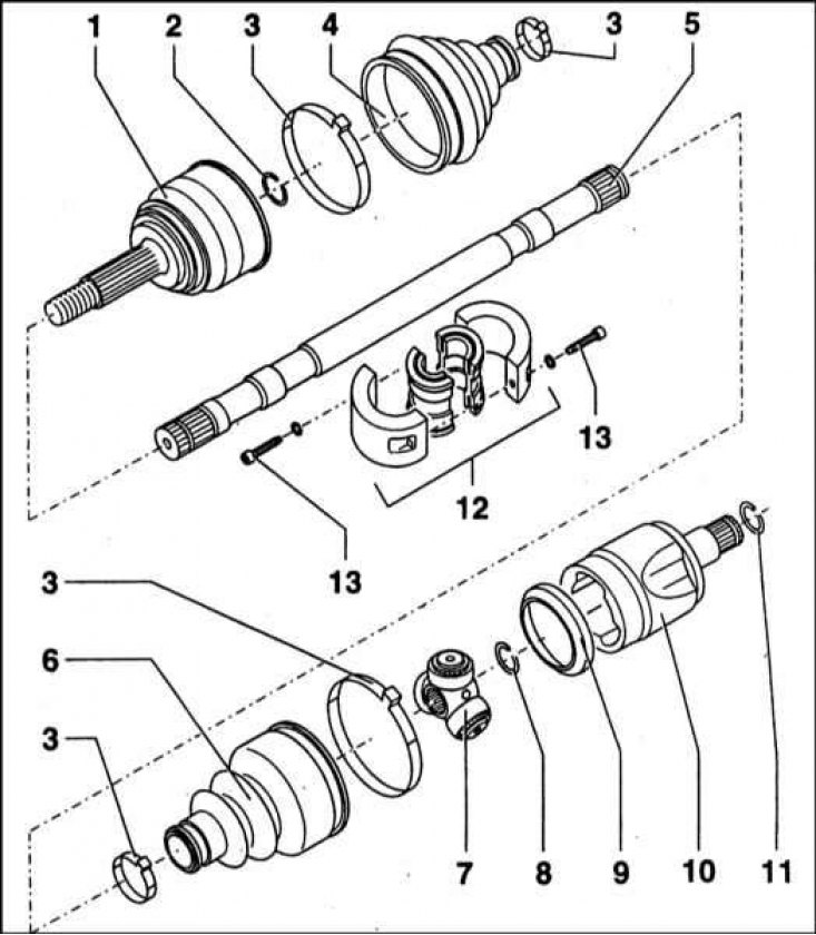
1 - Outer CV joint; 2 - Retaining ring; 3 - Bandage tape for fastening the protective cover; 4 - Protective cover; 5 - Drive shaft; 6 - Protective cover; 7 - Crosspiece of the tripod assembly of the outer CV joint; 8 - Retaining ring; 9 - Thrust ring; 10 - CV joint outer race; 11 - Retaining ring; 12 - Vibration damper (torsional vibration damper) right drive shaft; 13 - Allen bolt for socket wrench
The transmission of rotation from the differential of the main gear of the transmission to the drive wheels is carried out by means of two solid forged steel drive shafts. The outer ends of both drive shafts are equipped with splines that mate with the splines of the hubs of the drive wheels of the car. A large nut is used to secure the shaft in the hub. The inner ends of the shafts also end with splined journals that mate with the side gears of the differential. The left shaft is shorter than the right one due to the asymmetrical location of the main gear relative to the longitudinal axis of the car. The right (longer) a vibration damper is included, located at a distance of 105 mm from the edge of the protective cover of the inner CV joint, and is designed to dampen torsional vibrations of the assembly during its rotation. The design of the drive shaft is shown in the accompanying illustration. After forging, the drive shafts are hardened in a special way, which gives them increased strength.
Constant velocity joints (CV joints) are installed at both ends of each shaft. The joints ensure stability and smoothness of drive rotation at any angle of the wheels, determined by the road surface relief, as well as during turns. Separator ball bearing assemblies are used as outer CV joints. The inner joints have a tripod design.
The article is located on the website: www.skodabook.ru