
Functional diagram of the Mono-Motronic system
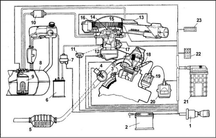
1 - MIgnition lock; 2 - Battery; 3 - Frequency and position sensor of the crankshaft; 4 - λ-probe; 5 - Catalytic converter; 6 - Coal adsorber; 7 - E / m valve of the fuel evaporation system; 8 - Fuel tank; 9 - Electric fuel pump; 10 - Fuel filter; 11 - Throttle position sensor; 12 - Coolant temperature sensor; 13 - Air cleaner; 14 - Fuel injection injector; 15 - Fuel pressure regulator; 16 - Air temperature sensor; 17 - Stepper motor of the idle system; 18 - Spark plug; 19 - Ignition distributor; 20 - ignition control ECU; 21 - ECU of the injection system; 22 - Fuses and relays; 23 - Diagnostic socket
Scheme of functioning of the injection injector and fuel pressure regulator
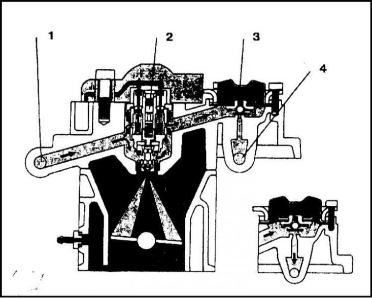
1 - Fuel supply from the fuel pump; 2 - injection injector; 3 - Fuel pressure regulator; 4 - Fuel return to the tank
The Bosch Mono-Motronic system belongs to the family of closed-loop motor control systems. Such systems control both direct fuel injection and fuel ignition.
The functional diagram of the Mono-Motronic system is shown in the illustration. The main components of the injection system include: a fuel tank with a submersible electric gasoline pump installed inside it, a fuel filter, fuel supply and return lines, a throttle body with an electronic fuel injection built into it, as well as an electronic control unit (ECU) complete with information sensors, actuators and connecting wiring.
The fuel pump provides a continuous supply of fuel through a cartridge-type filter into the throttle body under slight overpressure. The fuel pressure regulator built into the throttle body ensures a constant pressure on the injection injector. Excess fuel is returned to the fuel tank through the return line. This continuous supply system reduces the temperature of the fuel and prevents its evaporation.
The injector is opened and closed at the command of the ECU, which calculates the moment and duration of injection based on the analysis of incoming information signals about engine speed, throttle position and speed, intake air temperature, coolant temperature, vehicle speed, exhaust gas composition, etc.. The illustration shows the operation of the injection injector and fuel pressure regulator.
The air sucked into the engine passes through the air cleaner, inside which a replaceable filter element made of thick paper is installed. The intake air temperature is controlled by a vacuum valve located inside the air cleaner intake duct, which allows outside air to mix with the intake air through the heater shroud above the exhaust manifold. The position of the damper flap is controlled by a temperature-sensitive sensor-switch installed inside the air cleaner.
Information about engine speed enters the ECU from the Hall sensor mounted on top of the gearbox housing and fixing the speed of the flywheel.
The temperature of the air entering the throttle body is measured by a sensor mounted directly above the injection injector. The information is sent to the ECU, which, based on its analysis, determines the current needs of the engine in terms of injection timing and the composition of the air-fuel mixture.
The engine idle speed is controlled partly by the electronic throttle position module mounted on top of the throttle body, and partly by the ignition system, by changing the ignition timing settings. In view of the foregoing, the need for manual speed adjustments disappears and the possibility of its design of the system is not provided. Throttle position and speed information is supplied to the ECU by a special sensor, sometimes also referred to as a throttle potentiometer. The sensor is located on the left wall of the throttle body.
The oxygen content in the exhaust gases is continuously monitored by the ECU through a λ-probe installed in the front section of the exhaust system. Analyzing the incoming information, the ECU issues commands to adjust the ignition timing and injection duration, thereby forming the optimal composition of the air-fuel mixture. As a result, the need for manual adjustment of the CO content in the exhaust gases is also eliminated. All models covered in this manual come standard with a catalytic converter.
In addition to these functions, the ECU controls the operation of the evaporative emission control system.
It should be noted that diagnostics of failures of the Bosch Mono-Motronic system is possible only with the help of a special electronic reader. The diagnostic connector for connecting the reader is located on the right side of the car's instrument panel. In the event of any malfunction of the system, you should immediately contact the specialists of the Skoda branded service center, who will read and decrypt the codes recorded in the ECU memory unit, detected by the self-diagnosis system.
The procedure for replacing failed system components is described in the following Sections of the Chapter.
Precautionary measures
Warning! Gasoline is a highly flammable liquid. Special precautions must be observed when servicing power system components!
Do not smoke and do not approach the work area with an open flame source / unprotected carrier! Do not service power system components in rooms equipped with natural gas-fired, pilot flame-equipped heaters. Keep a charged fire extinguisher handy at all times.
Avoid getting fuel in eyes and on exposed skin. Wear protective gloves and goggles. Wash off accidental splashes with soap and water.
Remember that fuel vapors are no less, if not more, dangerous than liquid fuel itself. Do not forget that empty containers of gasoline still contain fuel vapors, which are not only highly flammable, but also potentially explosive!
Many of the procedures described in this chapter involve the need to disconnect fuel lines, inevitably leading to fuel spills. Try to prepare in advance all the necessary materials to collect spilled fuel.
Remember that residual pressure continues to be present in the system path even a long time after the engine has stopped. This pressure must be safely relieved before removing or disconnecting any of the fuel path components (see Section Release of residual pressure in the power system).
When servicing the components of the power system, pay special attention to cleanliness - the ingress of dirt into the fuel path can lead to a violation of its patency, leading to interruptions in the operation of the engine and even its spontaneous stops.
In the interests of the operator's personal safety and equipment safety, many of the procedures described in this chapter should only be performed after the negative cable has been disconnected from the battery. Such a precautionary measure, first of all, eliminates the possibility of a short circuit, and secondly, it helps to avoid voltage surges in the circuits of the electronic part of the engine control system, many of the components of which (such as ECU, sensors and actuators) highly sensitive to the overloads associated with such surges.
Note, however, that the system has a certain flexibility, allowing it to adapt to changes in the characteristics of the engine associated with its wear during the operation of the vehicle. This adaptability is associated with the presence in the memory of the ECU of certain parameters. When the battery is disconnected, this information is erased and after starting the engine, its restoration requires a small amount of time. The rehabilitation period may be accompanied by a violation of the stability of the engine speed, a decrease in sensitivity to a change in the throttle position, a slight increase in fuel consumption, etc. The duration of the recovery process is determined by the frequency of use and the operating conditions of the vehicle.