



Note: The gearbox must be mounted vertically on the mounting stand, the hole for the coupling must point upwards. Only in this way can the axial clearance of the clutch be correctly adjusted in the future. The gearbox must be securely fixed in the assembly stand -MP9-101- and must not turn. A large disc cage is inserted into the clutch in all discs, it must not slip out of the lowest disc. Transmission oil pump input shaft removed. Do not install deformed circlips.
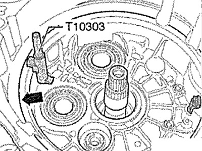
First install the locking bolt -T10303- in the seat -see illustration. arrow-clutch housing covers.
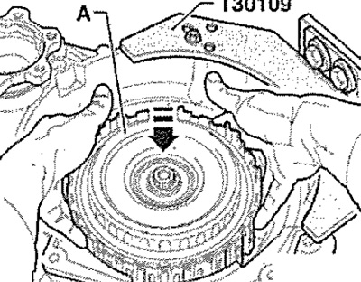
Then carefully fit clutch -A- in -direction of arrow-; protect from falling.
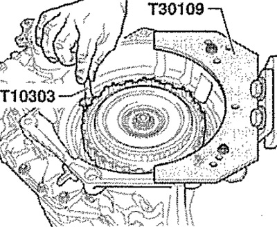
While doing this, a second mechanic must hold the locking bolt -T10303-. Retaining bolt -T10303- remains there until clutch housing cover is installed.
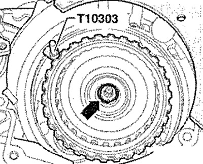
Select a 2 mm thick ring from all the circlips included in the scope of delivery - see. arrow- and temporarily install it. Before removing this ring, two measurements must be taken.
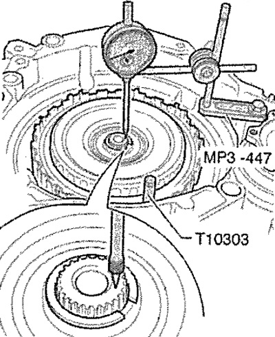
First dimension
Retaining bolt -T103D3- remains in place! Screw on the indicator universal bracket -MP3-447 (VW 387) - on the gearbox flange. Install the indicator probe on the gearbox input shaft. Set the dial indicator with a preload of 1 mm to 0. Raise the clutch up to the stop and record the measurement.
Second dimension
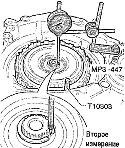
Retaining bolt -T10303- remains in place! Install the indicator gauge on the hub of the large clutch disc cage.
Note: The feeler gauge must not rest on the circlip.
Set the dial indicator with a preload of 1 mm to 0. Raise the clutch up to the stop and record the measurement. Now it is calculated which other new circlips are installed in the end. To do this, use the formula: Result of the second measurement minus the result of the first measurement plus 1.85 mm = thickness of the retaining ring to be installed.
Example
Record this result. The rest of the new retaining rings have different thicknesses in 0.1 mm increments. Measure all rings and determine the ring whose thickness best matches the result. Remove the ring with a thickness of 2 mm and replace with a ring with a certain thickness. Send all other rings for recycling.
Note: Retaining rings can only be installed once.
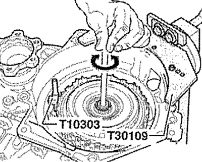
Insert input shaft for gear oil pump while turning slightly -in direction of arrow-.
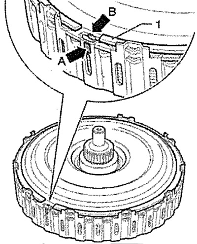
Insert the cover of the clutch housing so that the protrusion - see. arrow B- closed with a mark - see. arrow A-. Fit new circlip -1- into clutch.
Remove retaining bolt -T10303-. Install the clutch housing cover. This completes the installation, the clutch is correctly adjusted.
After installing the CP
Carry out basic measurement of mechatronics for dual clutch gearbox -J743- using.