
Pressing out the cover with the master rotor
CP removed. Remove flywheel.
Instruction. For a better idea, the procedure is shown with the engine removed.
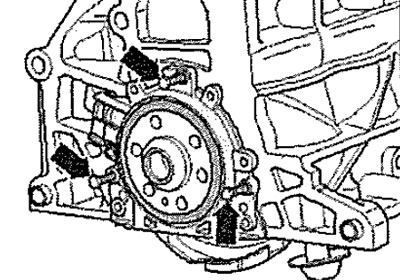
Remove intermediate plate from crankshaft rear cover and dowel sleeves -arrows-. By rotating the crankshaft by the toothed pulley mounting bolt, set the crankshaft to the "TDC"1 position. Remove oil pan. Remove engine speed sender -G28-.
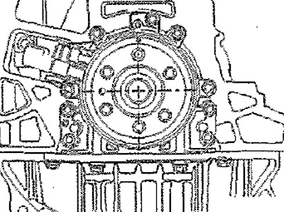
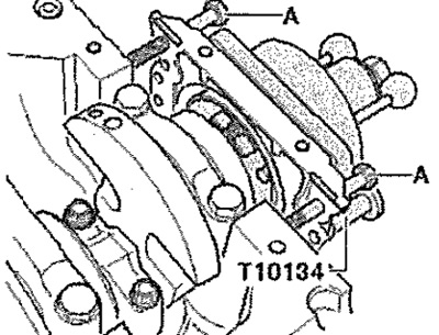
Remove bolts -1...6- securing crankshaft cover.
Note: The cover is pressed off the crankshaft together with the input rotor.
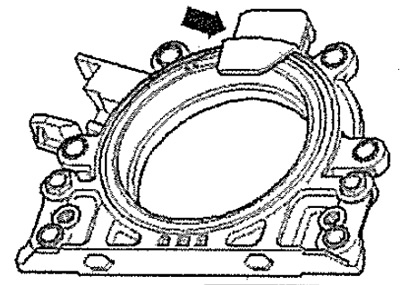
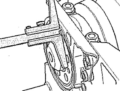
To press out, screw M6x35 screw -arrows- into crankshaft cover 3, alternately tightening each by no more than 1/2 turn. Remove the cover with the master rotor.
Pressing in the cover with the master rotor
Note: The crankshaft cover with PTFE lip seal is supplied with a support ring for the sealing lip. Do not remove this ring before installation, because. when installed, it will play the role of a mandrel. After removing the cover with the master rotor from the package, do not remove the rotor from the cover and do not turn it relative to the cover. The correct installation position of the feed rotor is ensured by the fixing device -T10134-. The bonnet, lip seal and drive rotor form a single unit and should only be replaced as an assembly. The assembly tool -T10134- is brought into the installation position relative to the crankshaft by means of a guide pin which is inserted into the hole in the crankshaft.
Assembly tool -T10134-
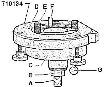
A. Lead screw flat
B. Hex nut
C. Housing
D. Retainer
E. Hex socket screw
F. Guide pin for diesel engines (black pen)
G. Guide pin for gasoline engines (Red pen)
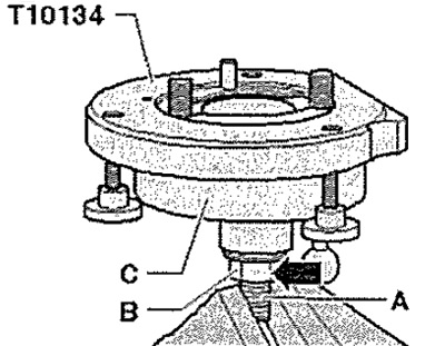
A. Installing the crankshaft cover with the driving rotor on the tool -T10134-
Unscrew hexagon nut -B- almost to the flats -A- of the spindle shank. Use a vice to clamp the assembly tool -T10134- in the area of the clamping surface -A- of the spindle. Push housing -C- down until it rests on hexagon nut -B- -arrow-. The interior and body of the fixture must be on the same level.
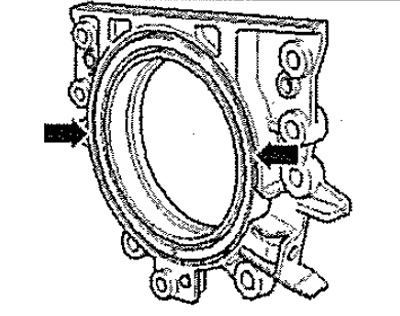
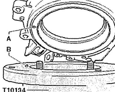
Remove safety catch -arrow- from new crankshaft cover.
Note: Do not remove or turn the drive rotor from the cover.
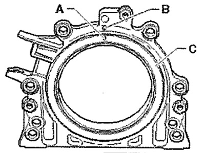
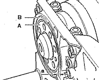
The locking hole -A- on the drive rotor -C- must be opposite the mark -B- on the crankshaft cover. Place the lid on a clean, flat surface on the front (outdoor) side down.
Press support ring -A- down -arrow- until it rests on a level surface.
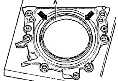
The top edge of the feed rotor and the front edge of the cover must be at the same level -arrows-.
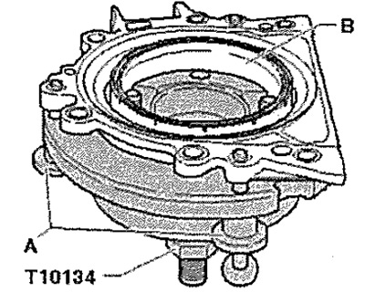
Place the cover with the front side on the tool -T10134- so that the locking pin -B- engages in the hole -A- of the feed rotor. The cover must lie flat on the mounting fixture.
While constantly pressing the cover and the support ring -B- against the surface of the tool -T10134-, tighten the two knurled screws -A- so that the locking pin cannot slip out of the hole in the feed rotor. Only two knurled screws are used - top and right, the left knurled screw does not fit the threads on the crankshaft cover. When installing the crankshaft cover, the driving rotor must remain fixed in the mounting tool at all times.
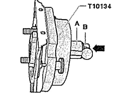
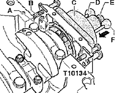
B. Installing tool -T10134- with cover on crankshaft flange
The crankshaft flange must be degreased. The engine is set to "TDC". Unscrew hexagon nut -B- to the end of the spindle. Press spindle of tool -T10134- in -direction of arrow- until hexagon nut -B- rests against housing -A-.
Align the flat side of the housing with the mating plane of the cylinder block on the oil pan side. Attach assembly tool -T10134- to crankshaft flange by screwing in hexagon socket screws -A- by approx. 5 threads.
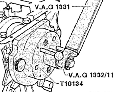
Screw 2 screws M7 x 35 mm -pos, A- into the cylinder block, which will play the role of guides for the crankshaft cover.
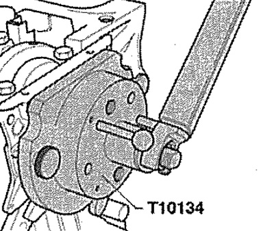
C. Screwing assembly tool -T10134- onto crankshaft flange
Move housing -C- by hand in -arrow- until support ring -B- rests against crankshaft flange -A-.
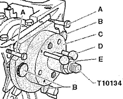
Attention! Danger of mixing up details. Never insert the dowel pin for petrol engines (red handle) -F- into the threaded hole of the crankshaft.
Insert dowel pin for diesel engine (black head) -D- into the hole in the crankshaft, this ensures the final installation of the driving rotor. Tighten both hexagon socket screws of the mounting tool by hand. Screw hexagon nut -E- onto spindle by hand until it touches tool body -C-.
D. Pressing the input rotor onto the crankshaft flange using assembly tool -T10134-
Tighten hexagon nut of tool -T10134- to 35 Nm. After tightening the hex nut to 35 Nm, there should be a small gap between the cylinder block and the flange.
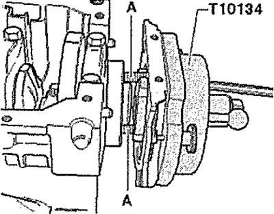
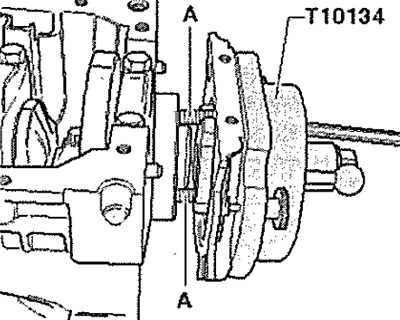
E. Checking the installation position of the driving rotor on the crankshaft
Unscrew hexagon nut -E- to the end of the spindle. Remove bolts -A- from cylinder block. Remove knurled screws -B- from crankshaft cover. Unscrew hexagon socket screws. Remove assembly tool -T10134- from crankshaft flange by unscrewing hexagon socket head screws from crankshaft flange. Remove tool -T10134-, Remove retaining ring.
Position depth gauge -VAS 6082- on crankshaft flange.
Measure protrusion -A- of crankshaft flange in relation to drive rotor -B-. Nominal value: dimension -a- = 0.5 mm. If the dimension -a- is too small, the drive rotor must be repressed. If the set value is reached, carry out further installation.
F. Re-pressing the master rotor
Attach assembly tool -T10134- -pos. A - on the crankshaft flange, tightening the hexagon socket bolts by hand. Move the tool to the crankshaft cover by hand.
Screw hexagon nut -E- onto spindle by hand until it touches tool body -C-. Tighten hexagon nut of tool -T10134- to 40 Nm. Again check the correct position of the driving rotor on the crankshaft. If dimension "ab" is still too small, tighten hexagon nut of tool -T10134- to 45 Nm. Again check the correct position of the driving rotor on the crankshaft.
Assembly
Installation in reverse order. Install oil pan. Install intermediate plate. Install flywheel.