
Stoplights
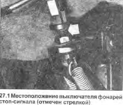
1. The brake light circuit is closed by a plunger-type switch mounted on the brake pedal bracket (see photo).
2. Check and adjust switch setting as described in Chapter 26 of this Section.
3. If there is a suspicion that the switch is faulty, check it. by disconnecting the wires and connecting a multimeter to its contacts (in resistance measurement mode). The circuit breaker should only close when its plunger is extended. Replace defective switch.
4. To remove the switch, disconnect its wires and loosen the lock nut, then wring out the rubber seals (as needed), to release the switch from the pedal bracket.
5. Install in reverse order of removal. Finally, adjust the switch setting (see chapter 26).
Handbrake warning lamp
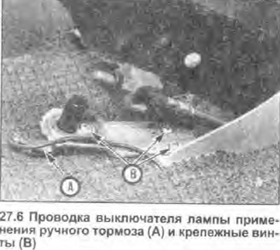
6. The handbrake indicator lamp circuit is closed by a plunger-type switch located at the base of the handbrake lever so that the lamp lights up whenever the lever is applied (see photo).
7. Release the plastic cover of the handbrake lever from the fasteners to gain access to the switch (see section 1).
8. The position of the switch cannot be adjusted, it is fixed with a screw to the mounting bracket, which, in turn, is held in position by two screws. To remove the switch, unscrew the screws and disconnect the wiring.
9. Use the method described in step 3 to check if the switch is working properly. Make sure the switch only closes when its plunger is extended. If the switch is defective, replace it.
10. Install in the reverse order of removal. Place the switch stem directly under the handbrake lever, then tighten the mounting screws.
Brake fluid level warning lamp
11. The liquid level warning lamp circuit is closed by a float-type sensor located in the filler cap of the master cylinder reservoir. The lamp lights up whenever the liquid level falls below a certain mark.
12. This lamp also comes on whenever the ignition key is turned to the «II» (engine starting), which serves as confirmation of its correctness. If the lamp does not light up when starting the engine, first check the lamp itself, then its wiring and troubleshoot (see Section 12).
13. To check if the sensor is working, remove it and use the method in step 3. Make sure the sensor circuit is only closed when the float is at the bottom of its stroke.
14. The sensor is sold only together with the filler cap of the master cylinder reservoir; if the sensor is defective, this assembly must be replaced.