



Contents: Inspection ⬇ Replacement ⬇
Warning: Brake pad sets on coaxial wheels should be replaced at the same time - never replace pads on just one wheel. This will result in uneven braking. Please note that dust generated by pad wear may contain asbestos, which is harmful to health. Never blow off dust with compressed air and try to avoid breathing it. DO NOT use petrol-based solvents to clean brake components. Use only special cleaner or methylated spirits.
Inspection
1. Remove and inspect the brake drum (see Chapter 20).
2. Carefully (see warning above) remove all traces of dust from the brake drum, its support shield and shoes, resulting from wear of the shoes. Make sure that the brake linings of the shoes are not contaminated with oil or grease, which happens when maintenance is carried out carelessly. To protect the brake lining of the shoe from such contamination, you can use adhesive tape or something similar, provided that its adhesive layer itself does not contaminate the material. Do not forget to remove the tape from the shoes before installing the drum.
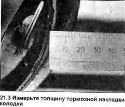
3. Measure the thickness of the brake pads in several places (see photo). If at least one of the pads in any place is worn to the specified Specifications minimum thickness, all four pads must be replaced (see warning above). The pads should also be replaced if any of them are contaminated with oil or grease. There is no effective way to degrease the brake pad linings.
4. If one of the brake pads is worn unevenly or is contaminated with oil or grease, find and correct the cause before proceeding with assembly.
5. Carefully lift each of the rubber protective covers to check the wheel cylinders for leaks and signs of corrosion and ensure that the plungers and pistons move freely (see Chapter 22).
6. Apply a small amount of brake grease (see point 17) on the hinge joints and working surfaces of the self-adjusting slack compensator/handbrake mechanism, then make sure that the compensator/mechanism operates properly.
7. Install the brake drum (see Chapter 20).
8. Repeat the procedure on the opposite brake.
Replacement
Note: The leading brake shoe of each rear brake assembly is the shoe that is closest to the rear of the vehicle in relation to the wheel cylinder - these shoes are different from each other and must be installed strictly on the brake assembly for which they are intended. The second shoe of each assembly is the driven shoe, these shoes are the same for the left and right rear brakes.
9. Remove and inspect the brake drum (see Chapter 20).
10. Carefully (see warning above) remove all traces of dust from the brake drum, its backing plate and shoes resulting from wear of the brake linings. Press the toothed segment of the self-adjusting clearance compensator to move the shoes away from the drum.
11. Unhook the handbrake cable (compressing its spring) from the working lever on the driven brake shoe.
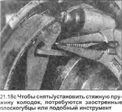
12. Using needle-nose pliers or similar tool, release the lower brake shoe tension spring.
13. Remove the brake shoe support posts by pressing on their free ends to release them.
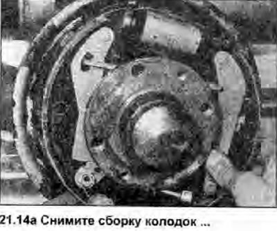
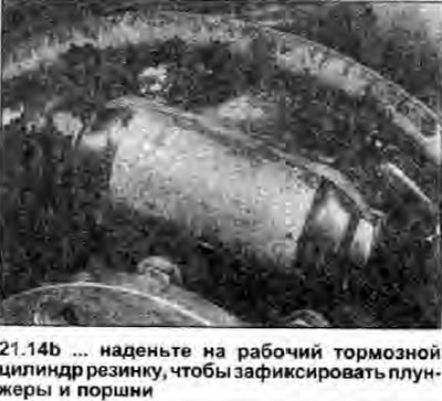
14. Unhook the self-adjusting slack adjuster/handbrake assembly components as needed and remove the brake shoes. Do not apply the brake pedal until the brake assemblies are assembled. Place a tight rubber band or similar on the wheel cylinder to secure the plungers and pistons in place (see photo).
 |
 |
15. Place the assembly on a clean work surface and unhook the upper shoe return spring. Separate the brake shoes and disassemble the self-adjusting slack adjuster/handbrake assembly by removing the associated spring and locking clips. Clean all components, inspect them for wear or damage and replace any that are unsuitable for further use.
16. Bend back the rubber protective covers, check the wheel cylinder for damage and tightness, and make sure that the plungers and pistons move freely in it (see Chapter 22).
17. Clean the drum brake backing plate and apply a small amount of high temperature brake grease or anti-lock compound (for example Holts Copaslip) on all working surfaces and hinge parts, as well as on areas and components that contact the shoes, especially on the plungers of the working brake cylinder and the lower guide of the brake shoes. Do not allow the grease to drip onto the brake pads of the shoes. To protect the brake pad from such contamination, you can use adhesive tape or something similar, provided that its adhesive layer does not itself contaminate the material. Do not forget to remove the tape from the shoes before installing the drum.
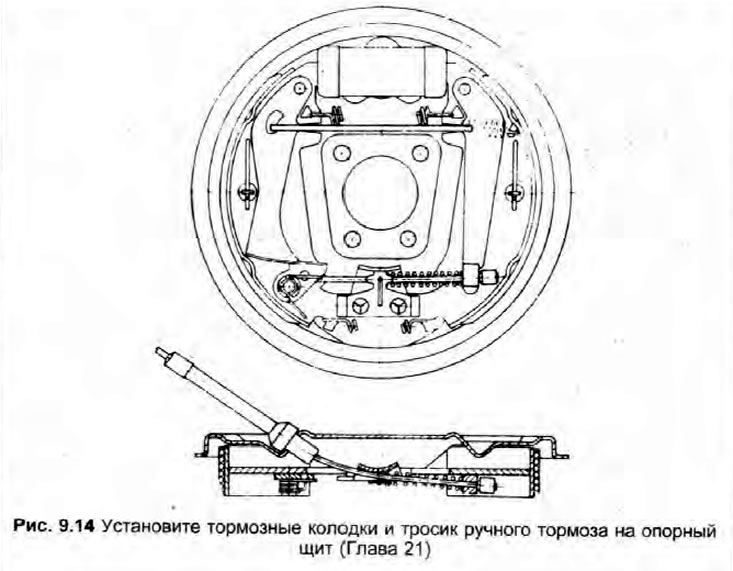
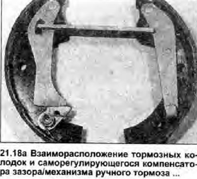
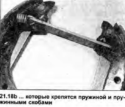
18. When installing, assemble the shoes and self-adjusting slack adjuster/handbrake mechanism on a clean work surface (see photo). Note that the upper shoe tension spring should be hooked with the shorter hook end to the leading brake shoe.
 |
 |
[View the original on the website: www.SkodaBook.ru]
 |
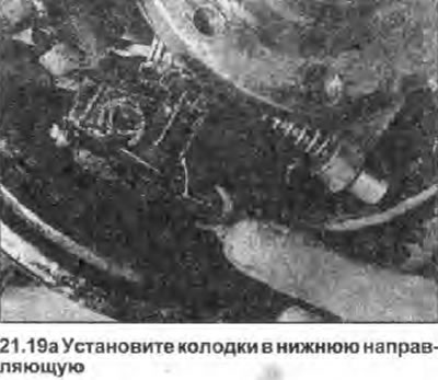
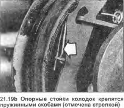
19. Install the assembly onto the drum brake backing plate, being careful not to get any grease on the brake linings. Make sure the shoes are seated properly in the plungers of the wheel cylinder and the lower guide, then install the shoe support posts and spring clips (see photo). Tap the shoes to center them on the drum brake backing plate.
 |
 |
20. Compress the return spring and connect the handbrake cable to its operating lever, making sure that the cable passes through the guide located in the brake support shield.
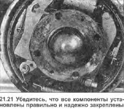
21. Attach the lower brake shoe tension spring. Make sure all components are correctly installed and securely fastened (see photo).
22. Remove the adhesive tape (if used) from the brake pads and the rubber from the working brake cylinder, then install the brake drum (see Chapter 20).
23. Repeat the procedure on the opposite brake.
24. Keep in mind that new pads need to be bedded in, so the car will need to travel several hundred kilometers before maximum braking efficiency is achieved. Avoid heavy braking during this period as much as possible and be prepared for longer stopping distances.