
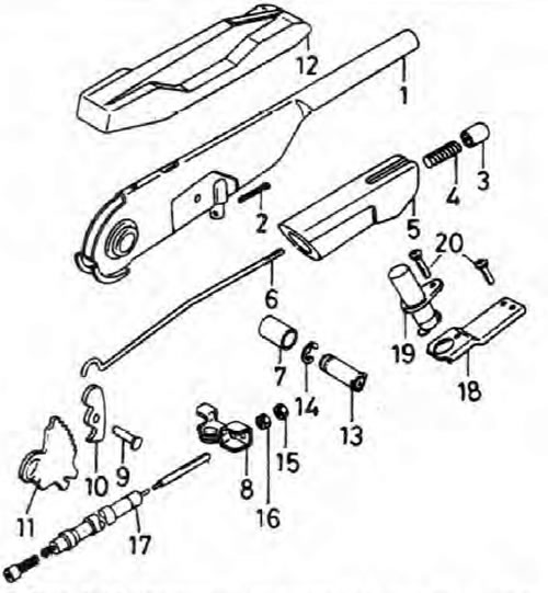
Pic. 9.17. Handbrake Components
1. Handbrake lever; 2. Cotter pin; 3. Release button; 4. Spring; 5. Handle; 6. Traction; 7. Articulated bushing; 8. Cable compensator; 9. Articulated pin (rivet); 10.Latch lever; 11. Toothed segment; 12. Plastic casing; 13. Hinge part of the lever; 14. Retaining ring (where available); 15. Locknut; 16. Adjusting nut; 17. Handbrake cable; 18. Mounting bracket; 19. The switch of a control lamp of application of a manual brake; 20. Screw.
Removing
1. Park your car on level ground (not slanted), turn off the ignition, select first gear or reverse, and block the wheels so that the vehicle cannot move after the handbrake is released.
2. Loosen the plastic cover on the handbrake lever, then loosen the adjusting nut and locknut to disengage each cable from the lever (see section 1).
3. If the lever pivot is secured on one side with a circlip, remove the circlip and extrude the pivot to release the lever assembly. If the retaining ring is not used, cut the hinge part with a hacksaw and purchase a new component to assemble (with retaining ring).
Installation
4. Install in the reverse order of removal. Apply a small amount of lubricant to all hinge parts, cable compensator joints, and adjuster threads. Adjust handbrake (see section 1).