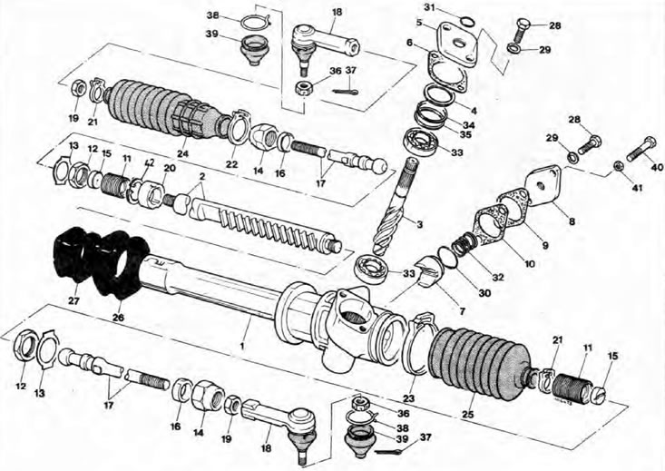
Fig. 10.14. Steering gear components
1. Steering gear housing; 2. Rail; 3. Gear; 4. Spacer gasket (if any); 5. Gear cover; 6. Gasket; 7. Stubborn heel; c. Thrust heel cover; 9. Gasket; 10. Gasket (if required); 11. Gearbox bushing; 12. Lock nut; 13. Lock washer; 14. Clutch sleeve; 15. Nest; 16. Insert; 17. Transverse steering rod; 18. Ball joint of the transverse steering rod; 19. Ball joint lock nut; 20. Rack bushing; 21. Outer bracket of the protective cover; 22. Inner bracket of protective cover (left); 23. Inner bracket of protective cover (right); 24. Left rubber protective cover of the steering gear; 25. Right rubber protective cover of steering gear; 26. Steering gear mounting rubber bushing; 27. Steering gear mounting rubber bushing; 28. Bolt; 29. Washer; 30. O-ring seal; 31. Seal (o-ring seal); 32. Spring; 33. Bearing; 34. Gasket (if required); 35. Gasket (if required); 36. Nut; 37. Hairpin; 38. Retaining ring; 39. Dust cover; 40. Heel rest adjuster; 41. Lock nut; 42. Retaining ring.
Note: Before you begin overhauling the steering gear, find out the price and availability of individual components, as well as the prices of a new or reconditioned unit, as overhauling may not be cost-effective. Also, read the procedure carefully and prepare all the necessary tools
Disassembly
1. Remove the steering gear from the vehicle (Chapter 18).
2. Clean the assembly thoroughly, prepare a clean work surface and keep it clean. Gently clamp the steering gear in a vice with soft pads. Pull the dust cap off the pinion shaft, then release the clamps and remove the rubber protective boots from the housing.
3. First, set the steering rack exactly to the middle of the stroke, which will correspond to the position of the wheels for driving straight. Then proceed as follows.
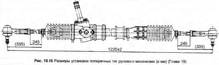
4. Rotate the pinion until the rack reaches its maximum length on one side, and measure the distance between the tie rod ball joint and a certain point on the housing. Move the rack in the opposite direction, and measure the distance between the same two points again. The difference between these two measurements will be equal to the full stroke of the rack; divide the stroke value by two and move the rack this distance, it should be in the center of the casing. Also check the conformity of the dimensions shown in Fig. 10.16.
5. Remove the steering rod ball joints and their locknuts (Chapter 20), then remove the rubber protective covers; drain all oil. Store the right and left side components in separate containers. It is recommended to install these components only in their original location (although some can be installed on either side, do not confuse them when assembling).
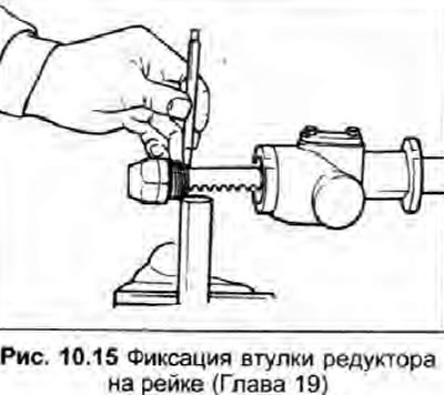
6. Using a power drill or similar tool, loosen the gearbox bushing at each end of the rack. While holding the bushing lock nut with a wrench, unscrew the gearbox bushings and separate the tie rods from the rack.
7. Bend the tabs of the lock washer with a screwdriver and unscrew the bushings from the lock nuts, then disassemble all components of each tie rod assembly.
8. Unscrew the rack stop cover from the housing, noting the number of gaskets underneath. Remove the spring, move the rack stop, and remove it by grasping the hole for the rack stop spring with pliers for removing retaining rings. Remove and discard the rack stop O-ring.
9. Unscrew the gear cover from the housing. Remove the cover, noting the gaskets underneath. On early models, the cover consists of a mounting plate and a cover with an O-ring seal between them; on later models, the cover also serves as a housing for the seal.
10. Remove the pinion shaft with the upper bearing. To do this, clamp the shaft in a vice with soft pads and gently tap on the upper side of the casing.
11. The lower pinion shaft bearing can be removed using a bearing puller. If the upper bearing needs to be replaced, use a suitable tool to remove it from the pinion shaft.
12. Remove the rack, then from the left end of the casing remove the retaining ring and the rack support sleeve, remember that there are mounting protrusions on the sleeve that must fit into the corresponding recesses in the gear casing.
Inspection
13. Thoroughly clean all components from dirt and old grease, and replace any that are worn or damaged. Roll the rack on a flat surface to check for distortion, then check the teeth on the rack and pinion. Check all bearings, bushings, and running surfaces for signs of wear. Replace all gaskets, seals, lock washers, and gearbox bushings whenever the mechanism is disassembled.
14. When assembling, carefully coat all components with the specified Specifications with grease; and fill the steering gear container and protective covers with it.
Assembly
15. Install the rack bushing and secure it with a new retaining ring.
16. To accurately install the gear and bearings, a special tool in the form of a blunt tubular drift, number MP 7-108, is used. If this tool is not available, the procedure described below in points 17, 18 and 19 can be used; note that if you warm the housing slightly first, the bearings will fit into the holes easily and will be correctly positioned with minimal risk of damage. Also, no excessive force will be required.
17. Drive the new lower pinion bearing into the housing until it stops, using a hammer and a tubular drift, which should rest against the outer race of the bearing.
18. Press the new upper bearing onto the pinion shaft until the inner race contacts the pinion teeth. Use a hammer and a tubular drift to do this, which should rest against the inner race of the bearing.
19. Drive the pinion with the upper bearing into the housing until the inner race of the lower bearing touches the teeth of the pinion. Use a hammer and a tubular drift to do this, which should rest against the outer race of the upper bearing, and make sure that the lower end of the pinion is without distortion in the lower bearing. Lubricate the pinion components.
20. Lubricate the rack and install it in place, making sure that the rack and pinion teeth are properly engaged; center the rack in the housing so that it is in the middle of the stroke (see point 4 above).
21. Fix the new gasket on the contact surface of the gear cover with grease, then measure the distance from the inner ring of the upper bearing to the upper side of the gasket. Select gaskets so that their total thickness is equal to the measured distance (maximum permissible deviation +0.10 mm) - there are gaskets with a thickness of 0.10 and 0.20 mm.
22. Install all gaskets, then install the cover components, and apply a few drops of sealant to the threads of the cover bolts. Tighten the bolts to the specified torque Specifications.
23. Move the rack from one extreme position to the other. Its movement should be smooth, without jerks and gear play. Return the rack to the middle position.
24. Grease the hole in the housing and the rack stop, install the stop and press it firmly against the rack: there should be no play between the rack and the stop. Install a new O-ring in the groove of the rack stop, then install the spring. Using a new gasket, install the cover. Loosen the adjuster lock nut, and unscrew the adjuster so that there is no pressure on the rack except for the rack stop and the spring.
25. Using a spring balance, measure the force required to move the rod back and forth. Perform the measurement three times and calculate the average; the regulated value is 110-130 N. If the measured force is less than 110 N, replace the spring and repeat the measurement: if more than 130 N, install another gasket between the cover gasket and the casing - a 0.2 mm thick gasket reduces the force by 20 N.
26. Lubricate the rack stop components and install the stop cover together with all selected gaskets. Tighten the cover bolts to the specified tightening torque Specifications.
27. With the rack in the middle position, gently squeeze the regulator by hand until you feel a steady pressure; in this position, all play between the rack stop, rack and pinion should be eliminated. Loosen the adjuster by 30°, apply a few drops of sealant to the threads and, holding it from turning, tighten the lock nut securely. Check again that the rack moves from one extreme position to the other easily and without jerking, then return it to the middle position.
28. Screw new gearbox bushings onto each end of the rack, then temporarily install and clamp the coupling bushings and locknuts onto them. Clamp one end of the coupling bushing and locknut in a vice, tighten both gearbox bushings (by installing the socket on the opposite sleeve of the coupling) tightening force, regulated Specifications. Fix the gearbox bushings by bending their edge into the groove at the end of the rack.
29. Unscrew the coupling bushings and attach the steering rods to them, installing new lock washers and coating the contact surfaces of the spherical journals, their sockets and inserts with lithium grease. To attach the transverse steering rod to the rack, first tighten the coupling bushing by hand.
30. Place the rubber protective boots on the steering rods, then install the locknuts and ball joints on the rods.
31. Screw the ball joint into the tie rod until the distance from the outer edge of the boot groove to the center of the ball joint is as shown in Fig. 10.16, then lightly tighten the lock nut of each ball joint; check that the distance from the outer edge of the groove for the protective cover to the inner edge of the lock nut is as shown in Fig. 10.16. Note that the marks made during removal should now be aligned.
32. Check that the distance between the centres of the two tie rod ball joints is as shown in Fig. 10.16. If it is necessary to change the position of the ball joints to adjust this value, make sure that each of them is screwed in the same number of turns; the final distance between the tie rod end to the ball joint centre/lock nut on both sides should always be the same, but a deviation of up to 3 mm from the value shown is allowed.
Note: This is a basic setting only, final alignment is performed with the steering gear installed in the vehicle.
33. If the vehicle needs to be rolled to check wheel alignment, tighten the ball joint locknuts securely; otherwise, be guided Chapter 21.
34. Clamp the housing in a vice with soft pads, hook a spring balance on the recess under the ball joint dust cap, clamp the coupling sleeve with a force of 12.5-20.5 N. Then, holding the coupling sleeve stationary, securely tighten the lock nut. Secure the assembly by bending the tabs of the lock washers onto the lock nut and onto the coupling sleeve, then repeat the procedure on the remaining tie rod.
35. Make sure the rack is in the middle position (centered in the casing), then use white paint to make alignment marks on the pinion shaft and housing so that when you install the steering gear into the car you can easily determine the center position of the rack. Install the dust cap on the pinion shaft, and make sure that the pins of both ball joints are facing down (i.e. in the correct position for installation in the car).
36. If the steering gear is filled with grease, place the rubber protective boots in the grooves on the steering rods and secure with the outer clips, then fill the remaining grease into the protective boots, place them in the grooves in the housing and secure with the inner clips.
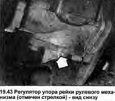
37. If the steering gear is filled with oil, first install one rubber boot and secure it with the clamps, then position the other boot in the housing groove and secure it with the inner clamp. Inject the remaining oil under the sealing lip of the boot and into the steering gear, and secure the outer clamp.
38. Install the steering gear into the vehicle (Chapter 18). If it becomes necessary to turn any tie rod, loosen the clamps and re-position the boot, then re-tighten the clamps, being careful not to lose grease.
Final adjustment of the rack stop
39. Whenever the position is disturbed, or in the event of a steering gear malfunction, check the installation of the rack stop as follows.
40. First, make sure that the tires are in good condition and have the correct pressure, and that the brakes do not lock the wheels.
41 Start driving straight, release the steering wheel and check that the car continues to move straight.
42. Turn the steering wheel slightly from the center position in either direction (approximately 20°), making sure that when released it returns to the straight-ahead position.
43. If the self-centering is slow or stiff, the rack stop must be adjusted as described above. Note, however, that you may have to remove the steering gear from the car, as the adjuster is difficult to access (see photo).