
Earbud selection
1. To select the required main bearings, you will first need to determine the size group of the crankshaft main journals. To do this, measure the diameters of the main journals and, based on the measurements obtained, Specifications determine their size group (see details in Chapter 14).
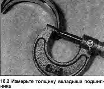
2. The size group of the crankshaft journals can be determined in another way. Measure the thickness of the old bearings using a suitable micrometer, then compare the readings with those in the table below (see illustration). It is preferable to still use crankshaft journal dimensions, as bearings are more difficult to measure accurately and are likely to wear out.
3. When the size group of the main journal is known, the correct bearings can be selected from the table below:
| Size group of the main neck | Liner thickness |
| Nominal | 2.495 mm |
| 1st repair | 2.620 mm |
| 2nd repair | 2.745 mm |
| 3rd repair | 2.870 mm |
Please note that all new liners have a manufacturing tolerance of +0.000 to -0.010 mm.
Checking the operating clearance of the main bearing
4. Clean the back side of the liners and their seats in the cylinder block/crankcase and covers.
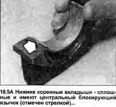
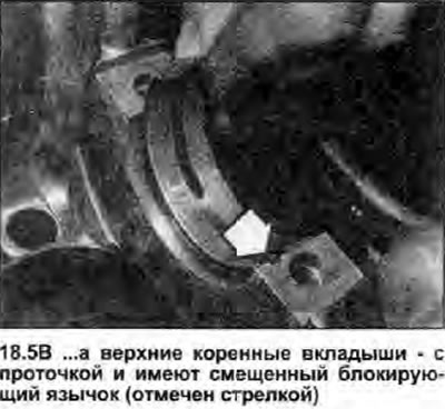
5. Insert the liners into their places, making sure that the tongue on the liner fits into the corresponding recess in the cylinder block or cover. Please note that it is not possible to interchange the positions of the upper and lower main bearings, as their blocking tabs are offset (see illustrations).
 |  |
6. If the old main bearings are used, they must be installed strictly in the old place in the cylinder block and covers.
7. Check the operating clearance of the main bearing if there is any doubt about the degree of wear of the crankshaft, if the crankshaft has been reground and installed with non-original repair liners. The gap can be checked in one of two ways.
8. First method (which is difficult to use without a set of calipers or expandable calipers); install the main bearing caps with liners in the cylinder block/crankcase. Tighten the bolts for fastening the covers with a tightening force regulated specifications, measure the inner diameter of each pair of bearings and the diameter of the corresponding crankshaft journal. The difference in diameter will be the working clearance of the main bearing.
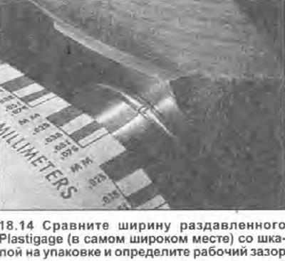
9. Second method (more accurate): using an American product known as the Plastigage special tool. It is made in the form of a fine-grained plastic wire of absolutely round cross-section, which is clamped between the bearing shell and the neck. After removing the liner, the width of the crushed plastic can be compared with the scale attached to the kit on a piece of cardboard. The working clearance is determined on this scale. The procedure using Plastigage is as follows.
10. Place the upper main bearings in place in the crankcase, carefully slide the crankshaft into position. Do not use lubricant; Crankshaft journals and liners must be perfectly clean and dry.
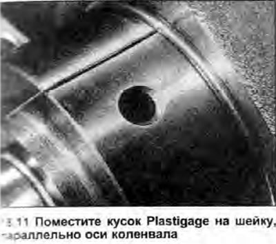
11. Cut three pieces of Plastigage to the appropriate size (they should be slightly shorter than the width of the main bearings) and place them on the crankshaft journals parallel to the axis (see illustration).
12. Install the main bearing caps with liners in place and press the fastening bolts with a tightening torque regulated specifications. Be very careful not to dislodge the Plastigage and do not rotate the crankshaft during this operation.
13. Carefully unscrew the bolts and remove the bearing caps, being careful not to disturb the position of the Plastigage and not to rotate the crankshaft.
14. Compare the width of the deformed thread with the scale. The working clearance is indicated on the scale (see illustration). Compare your result with the data given in Specifications.
15. If the gap is too large, the wrong size bushings are installed, or they are excessively worn (if old liners are reused). Before deciding that the crankshaft is worn, make sure that no dirt or oil has entered between the bearing shells and the caps or block when measuring the clearance. If one end of the Plastigage thread is wider than the other, the crankshaft journal may be tapered.
16. If the running clearance of the main bearing is excessive even with new liners of the correct size, it is necessary to regrind the crankshaft to the next repair size and install the appropriate repair main bearings (see chapter 14).
17. If all is well, carefully clean all traces of Plastigage from the crankshaft and liners.
Final installation
18. Gently lift the crankshaft out of the cylinder block.
19. Place the bushings into the slots as described in steps 4-6 above. If new bearings are installed, wipe off protective grease from them. Liberally lubricate each liner in the cylinder block/crankcase.
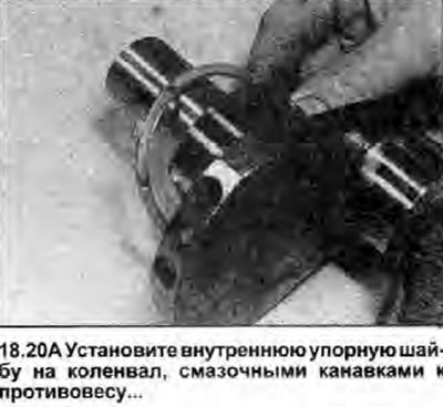
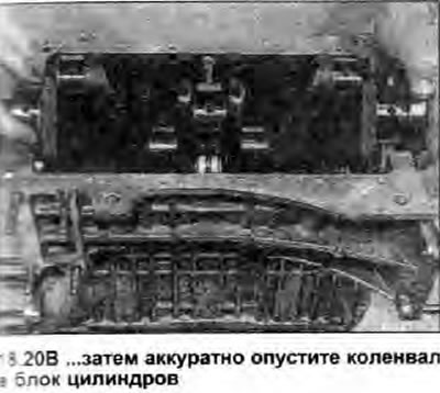
20. Slide the inner thrust washer onto the right end of the crankshaft with the oil grooves facing the crankshaft counterweight. Carefully lower the crankshaft to its operating position in the block, then coat the bearings and crankshaft journals with engine oil. Position the locking tab of the thrust washer so that it faces up; in this way it will be aligned with the slot in the bearing cap (see illustrations).
 |  |
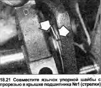
21. Establish covers of radical bearings on former places. Align the tab of the thrust washer with the slot in the rightmost bearing cap, and press the thrust washer into the notch (see illustration).
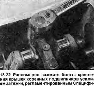
22. Establish bolts of fastening of covers of radical bearings, and clamp them in regular intervals the tightening effort regulated specifications (see illustration).
23. Make sure the crankshaft turns freely, then check the end play as described in Chapter 11. Carefully check that the locking tabs of the thrust washers are properly seated in the grooves on the cover before tightening the crankshaft pulley bolt.
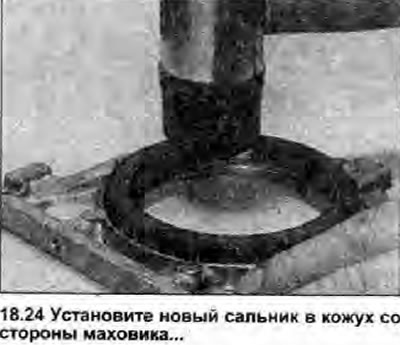
24. Remove traces of gasket or sealant from the contact surfaces of the cylinder block and the stuffing box on the flywheel side. Carefully remove the old seal from the housing and insert the new one. If necessary, use a mallet to drive the seal into place (see illustration). The sealing lip of the stuffing box must face inwards.
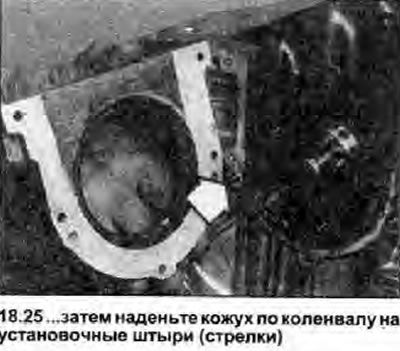
25. If a gasket was used on the stuffing box, install a new one on the pins in the cylinder block. If there was no gasket, apply a thin layer of sealant to the contact surface of the casing. Install the oil seal on the end of the crankshaft, taking care not to damage its sealing lip. Slide the shroud into position on the cylinder block so that it fits over the dowel pins (see illustration). Insert the cover screws and tighten them securely. If a gasket was installed, use a sharp knife to cut off the ends that stick out on the mating surface of the pan.
26. Install the connecting rod assemblies as described in Chapter 19.