
Removing
1. Remove the valve train as described in Chapter 5 of Section 2A.
2. Remove the push rods one by one and fold them in the correct order by pushing them into the cardboard holder.
3. Remove the four nuts securing the rocker arm cover to the front of the cylinder block, then remove the washers and seals from the cover studs. Carefully use a screwdriver to separate the cover from the cylinder block, and remove it together with the rubber seal.
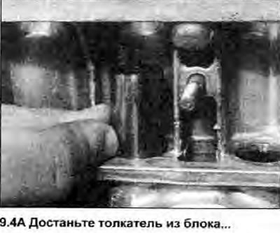
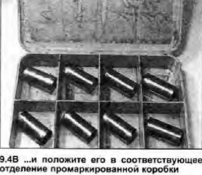
4. Take out all the pushers one by one and put them in a box with labeled compartments (see illustrations).
 |  |
5. Remove drive chain and sprockets as described in Chapter 7 of Section 2A.
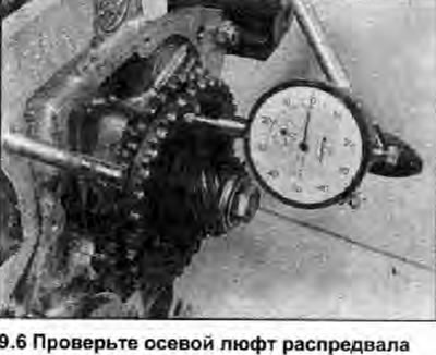
6. Before removing the camshaft, check its end play as follows. Temporarily install the distributor drive gear, concave and lock washers, and sprocket bolt onto the end of the camshaft, and tighten the bolt to the specified torque specifications. Fix the micrometer so that the probe is parallel to the axis of the camshaft and abuts against its end, measure the axial play by moving the camshaft along the axis, first in one direction and then in the other direction until it stops (see illustration). If the axial clearance exceeds the specified Specifications limit value, when installing, replace the camshaft bearing plate.
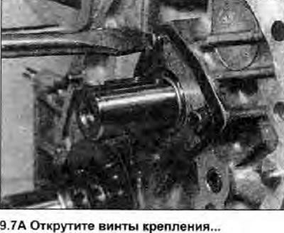
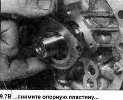
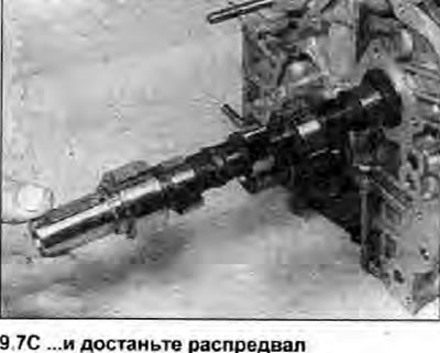
7. Remove the temporarily installed components, then unscrew the three screws securing the camshaft base plate to the cylinder block. Remove the plate and remove the camshaft from the block (see illustrations).
 |  |
 |
Inspection
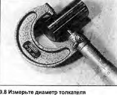
8. Inspect the tappets for gouges and corrosion on surfaces in contact with the camshaft lobes. Insert the tappets one by one into the corresponding holes in the cylinder block and check that they move freely up and down and that there is no excessive lateral movement. If you have the necessary tools, determine the wear of the pushers and their seats in the cylinder block (see illustration).
9. If any of the rocker arms is badly worn, the corresponding pusher must also be replaced. If excessive lateral movement is observed, or if any bore in the cylinder block is heavily worn, bore the cylinder block seats and install an oversized tappet. Have this job done by a Skoda dealer.
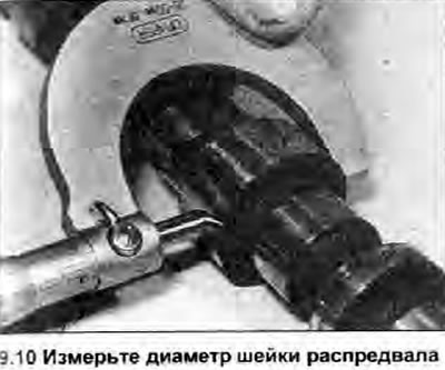
10. Inspect the camshaft lobes and bearing journals for signs of wear, corrosion, or scratches. If you have the necessary tools, measure the diameter of the camshaft journals (see illustration) and the inner diameter of each bearing in the cylinder block, and compare the results with those given in Specifications data. Bearing running clearance can be calculated by subtracting the diameter of the camshaft journal from the diameter of the opening formed by the bearing surfaces.
11. If the cams or necks are badly worn, replace the camshaft. If the camshaft bearings are excessively worn, consult a Skoda dealer or engine rebuilder for reboring the cylinder block and installing camshaft bearing shells. If this is not possible, the block must be replaced.
12. Inspect the camshaft bearing plate for wear and replace if worn.
Installation
13. Copiously lubricate the cams and camshaft journals with oil, then insert the camshaft into place in the cylinder block.
14. Install the base plate on the end of the camshaft, and securely tighten the three mounting screws. Check the end play of the camshaft as described in point 6.
15. Install drive chain and sprockets as described in Chapter 7 of Section 2A.
16. Copiously lubricate the outer surfaces of the tappets, and insert them into their respective seats in the cylinder block. If old tappets are used, install them strictly in the old places to minimize wear.
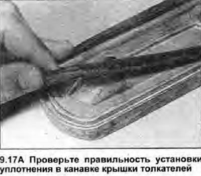
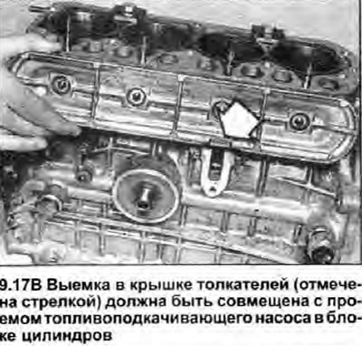
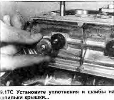
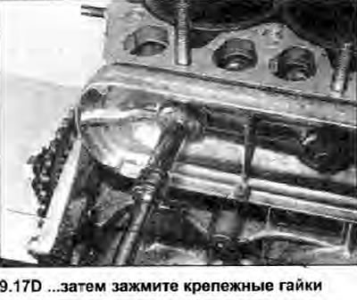
17. Inspect the pusher cover seal for damage or contamination and replace if necessary. Check that the contact surfaces of the cover and block are clean and that the seal is properly seated in the groove in the cover. Attach the cover to the cylinder block, the slot on the outer frame of the cover should be facing down and aligned with the opening of the fuel priming pump on the cylinder block. Install the seals and flat washers on the cover studs, then tighten the fixing nuts and tighten them to the specified torque specifications (see illustrations).
 |  |
 |  |
18. Insert the pusher rods into their original places in the cylinder head, making sure that they are correctly placed on the pushers.
19. Install the valve train and adjust the valve clearances as described in Section 1, Finally install the valve cover.