
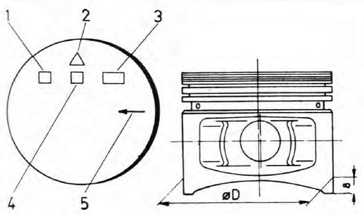
Pic. 2B.4. Piston head marking and diameter measuring point
1. Manufacturer's number
2. Manufacturer's mark
3. Piston size class (diameter)
4. Production date
5. Arrow (points towards the front of the cylinder block)
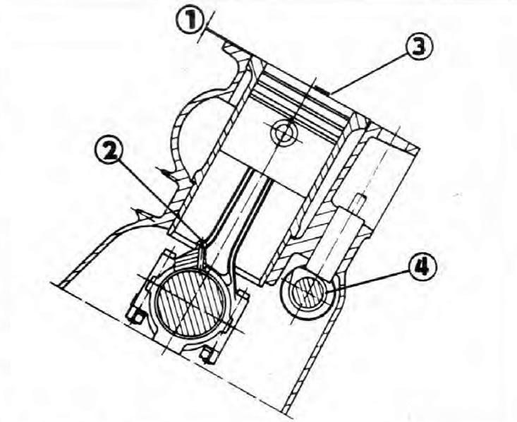
Pic. 2B.5. Cylinder block with installed crankshaft, piston, connecting rod and camshaft
1. Protrusion of the liner above the surface of the cylinder block
2. Oil channel of the connecting rod
3. Arrow on the piston head (points towards the front of the cylinder block)
4. Camshaft
Disassembly
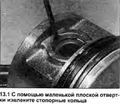
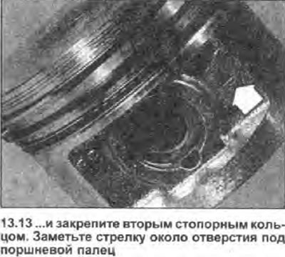
1. Using a small flathead screwdriver, carefully pry the circlips out of the piston pin hole and discard them (see illustration). Note the position of the arrow on the piston and the oil groove on the connecting rod (see point 11).
2. Push the piston pin out of the piston, then separate the piston from the connecting rod. If the piston pin is firmly seated in the piston, it will be easier to remove it if the piston is slightly warmed up.
Inspection
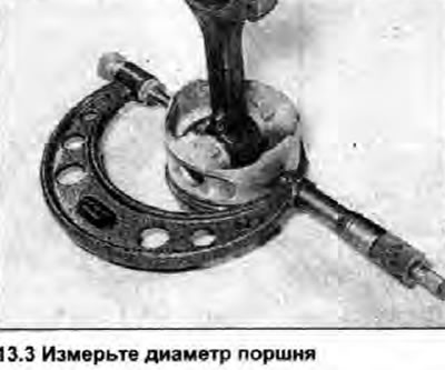
3. Check all pistons for out-of-roundness, scuffs, scratches and signs of wear in the ring grooves. Using a micrometer, measure the piston diameter at a distance of 8 mm from the base of the skirt, perpendicular to the axis of the piston pin. Check the stop between piston and cylinder wall as described in Chapter 12 (see illustration).
4. Replace the piston if it wears more than specified in Specifications tolerances for its size class. As mentioned in Chapter 12, all cylinder liners and pistons must be of the same size class. The piston class is imprinted on its head (see fig. 2B.4).
5. If new rings will be installed on the old pistons, remove the old ones from them (see illustration).
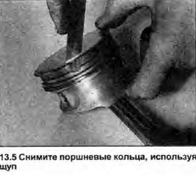
6. After the piston rings are removed, check the condition of the grooves in the piston and clean them of deposits using the old ring. Be careful, the edges of the ring can be very sharp.
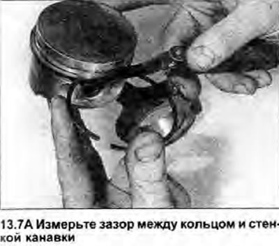
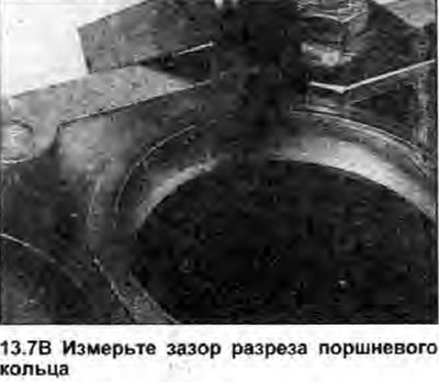
7. Check the gap between the ring and the groove wall by inserting each ring with a feeler gauge between the top of the ring and the groove wall. Check the gaps of the ring cuts by inserting the ring into the cylinder bore and push it with the piston head approximately 15 mm from the top edge, and then measure the gap with a feeler gauge (see illustrations). Desired clearance values for all rings are given in Specifications.
 |  |
8. Inspect the connecting rods for damage and make sure they are not bent. If any connecting rod shows signs of damage or is bent, replace it. Connecting rods are divided into two groups according to weight. The weight class is indicated by a colored dot on the connecting rod bearing cap: light connecting rods are marked with a yellow dot and heavy connecting rods with a blue dot. Skoda says all four connecting rods must be in the same weight class. If the weight mark is not visible, contact a Skoda dealer where the connecting rod can be identified by direct weighing.
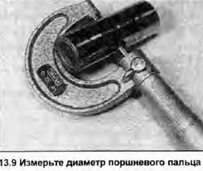
9. Inspect the piston pin and bushing in the top end of the connecting rod for signs of wear and tear. Insert your pin into the bushing and check that there is no visible play between them. If the necessary measuring tools are available, the condition of the bushing and piston pin can be determined by direct measurement; subtract the outer diameter of the pin from the inner diameter of the sleeve - get the backlash value (see illustration). If any part is worn or any measurement exceeds the Specifications tolerances, the piston pin and sleeve must be replaced as a matched pair. To replace the connecting rod bushing, see a Skoda dealer who is equipped with the necessary tools to do the job.
Assembly
10. Install a new retaining ring in one of the grooves in the piston pin hole. Lubricate the bore and insert the piston pin from the opposite end of the piston.
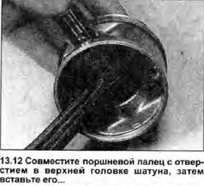
11. Insert the connecting rod into the piston, making sure that the arrow on the piston (on the head or next to the piston pin hole) pointed in the direction opposite to the lubrication channel on the connecting rod, i.e. so that the arrow points towards the front of the cylinder block. and the connecting rod lubrication channel to the rear (see fig. 2B.5).
12. With the piston and connecting rod oriented as above, align the hole in the top end of the connecting rod with the piston pin and insert the pin all the way into the piston until it rests against the retaining ring (see illustration).
13. Make sure the connecting rod turns freely on the piston pin, then secure the pin with a second circlip (see illustration).
14. Install the piston rings as described in Chapter 17.