
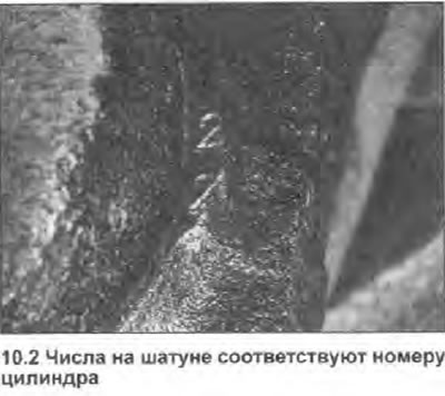
2. Before removing the cranks, notice the two numbers that are printed on one side of each assembly, one on the cap and one on the crank (see illustration). These numbers indicate the number of the cylinder in which the assembly is installed. Cylinder #1 is at the right end (next to the drive chain). If the numbers are not visible, make the marks yourself using a hammer and punch (or paint).
3. With the connecting rods installed on the crankshaft, use a feeler gauge to check the axial clearance between the crankshaft covers and counterweights. If the clearance greatly exceeds the Specifications tolerances, the connecting rods must be replaced.
4. Rotate the crankshaft until the pistons of cylinders 2 and 3 are at BDC.
5. Unscrew the nuts of the connecting rod bearing cap, and remove the cap together with the insert. If you need to check the liners, move the connecting rod away from the crankshaft journal, and remove the upper liner from it. Store cap, nuts and bushings together.
6. Similarly, remove the connecting rod covers of cylinders No. 1 and 4.
7. Remove the carbon ridge from the top of each cylinder bore. Push out the piston/rod assemblies and remove them through the top of the cylinders. Make sure the connecting rod ends do not scratch the cylinder walls. Install caps, bushings, and nuts on the connecting rods immediately so that all assemblies are stored as a consistent set.