
Note: If both drive shafts have been removed, do not move the vehicle or the front wheel bearings may be damaged. If it is absolutely necessary to move the vehicle, temporarily install the drive shafts and tighten their nuts, or preload the bearings by pressing the bearing inner race against the hub with a bolt, nut and washers. Before removing the driveshafts, check that the driveshaft internal circlips and nuts are commercially available, as well as other parts that may need to be replaced.
Removing
1. Without jacking up the vehicle, apply the handbrake and select first gear or reverse.
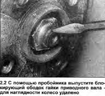
2. Remove the wheel center cap. Bend back the blocking rim of the drive shaft nut using a hammer and punch (see photo) or (if it is needed) electric drill. Using a suitable socket and a strong extension rod, loosen the nut, but do not unscrew it yet. If the nut is too tight, have an assistant depress the brake pedal.
3. Loosen the wheel bolts, then jack up the front of the vehicle and place it securely on axle stands. Remove the wheel, then unscrew the drive shaft nut. The nut must always be replaced after each removal.
4. Drain gear oil (see section 1).
5. Open the hood and loosen the two nuts on the upper suspension strut mounting one or two turns.
6. Disconnect the tie rod ball joint from the steering knuckle arm (see Section 10).
7. After removing the pinch bolt, disconnect the ball joint of the lower suspension arm from the steering knuckle (Section 10).
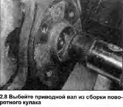
8. Pull the steering knuckle sharply towards you to remove it from the grooves of the drive shaft. It may be necessary to tap the driveshaft out of the hub with a mallet, after installing the old driveshaft nut to protect its threads (see photo). Be careful not to stretch or kink the brake hose.
9. Move the rack assembly along with the steering knuckle and brake caliper away from the end of the drive shaft and tie them to the body.
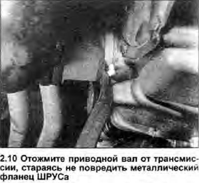
10. Using a suitable lever, push the drive shaft away from the transmission until the circlip compresses in its groove and out of the differential pinion gear (see photo). Be careful not to damage the metal flange on the inner end of the inner CV joint.
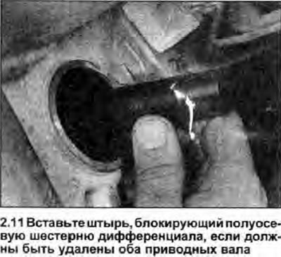
11. Remove the drive shaft assembly. If both drive shafts must be removed, block the differential side gear by inserting a clean metal rod or wooden pin approximately 24 mm in diameter into the transmission (see photo). Discard the retaining ring mounted on the inner end of the drive shaft - it must be replaced after each removal.
Installation
12. Thoroughly clean the drive shaft and openings in the transmission and steering knuckle to prevent dirt from entering these assemblies. Apply a light coat of grease to the sealing lips of the oil seal and to the grooves and ribs of the drive shaft. Make sure that all protective sleeve clamps are securely fastened.
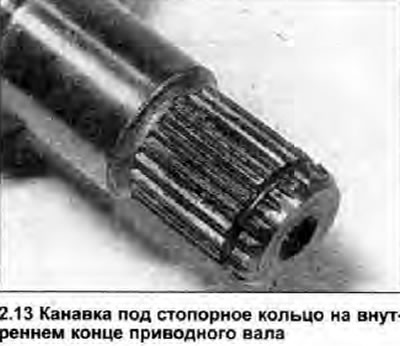
13. Install a new retaining ring on the inner end of each drive shaft and make sure that the rings fit into the grooves intended for them (see photo). Remove the pin blocking the differential side gear.
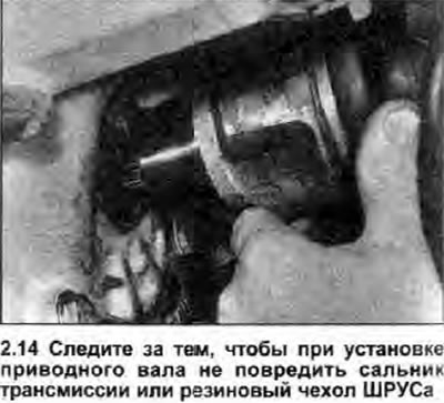
14. Being careful not to damage the sealing lips of the stuffing box, insert the drive shaft into the transmission and align its grooves with the grooves of the differential side gear. Push the drive shaft firmly into place until the circlip snaps behind the side gear. If necessary, use tools to drive the drive shaft into position, being very careful not to damage the rubber boot (see photo).
15. Make sure the shaft is securely held by the circlip. To do this, grab the CV joint housing and try to pull the drive shaft out of the differential side gear.
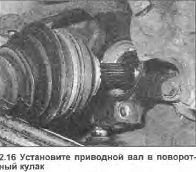
16. Install the drive shaft to the steering knuckle assembly (see photo) and screw in a new shaft nut.
17. Install the ball joint of the lower suspension arm into the steering knuckle, insert the coupling bolt and tighten the bolt nut with the torque specified specifications.
18. Connect the ball joint of the tie rod to the steering knuckle arm, tighten the joint nut with the torque specified specifications, and install a new cotter pin (see Section 10).
19. Install the wheel.
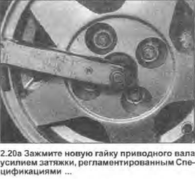
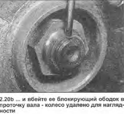
20. Lower the vehicle to the ground and tighten the driveshaft nut and wheel bolts to the specified torque specifications. Using a hammer and punch, secure the drive shaft nut by driving its locking rim into the shaft groove (see photo).
 |  |
21. Install the wheel center cap; where necessary, do not forget to tighten the remaining wheel bolts with the tightening torque specified specifications.
22. Fill transmission with oil (see section 1).